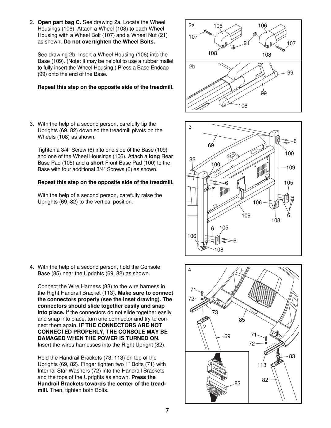
2. | Open part bag C. | See drawing 2a. Locate the Wheel |
| 2a | 106 | 106 | |||
| Housings (106). Attach a Wheel (108) to each Wheel |
| |||||||
|
|
|
|
| |||||
| Housing with a Wheel Bolt (107) and a Wheel Nut (21) |
| 107 |
|
| ||||
| as shown. |
| Do not overtighten the Wheel Bolts. |
|
|
| |||
|
|
|
| 21 | 107 | ||||
|
|
|
|
|
|
|
| ||
| See drawing 2b. Insert a Wheel Housing (106) into the |
| 108 | 108 | |||||
| Base | (109). (Note: It may be helpful to use a rubber mallet |
| 2b |
|
| |||
| to fully insert the Wheel Housing.) Press a Base Endcap |
|
| 99 | |||||
| (99) onto the end of the Base. |
|
|
|
| ||||
| Repeat this step on the opposite side of the treadmill. |
|
|
|
| ||||
|
|
|
|
|
|
|
|
| 99 |
|
|
|
|
|
|
|
| 106 |
|
3. With the help of a second person, carefully tip the |
|
| 3 |
|
| ||||
| Uprights (69, 82) down so the treadmill pivots on the |
|
|
| |||||
|
|
|
|
| |||||
| Wheels (108) as shown. |
|
|
|
| 6 | |||
|
|
|
|
|
|
| 69 | ||
| Tighten a 3/4” Screw (6) into one side of the Base (109) |
|
| ||||||
|
|
|
| 100 | |||||
| and one of the Wheel Housings (106). Attach a | long | Rear | 82 |
| ||||
|
|
| |||||||
| Base Pad (105) and a | short Front Base Pad (100) to the |
|
|
| ||||
|
| 100 | 109 | ||||||
| Base with four additional 3/4” Screws (6) as shown. |
| |||||||
|
|
|
| ||||||
|
|
|
|
| |||||
| Repeat this step on the opposite side of the treadmill. |
|
| 6 | 105 | ||||
| With the help of a second person, carefully raise the |
|
|
|
| ||||
| Uprights (69, 82) to the vertical position. |
|
|
|
| 106 | |||
|
|
|
|
|
|
|
| 109 | 6 |
|
|
|
|
|
|
|
|
| 108 |
|
|
|
|
|
|
| 6 | 105 |
|
|
|
|
|
|
|
| 106 | 6 |
|
|
|
|
|
|
|
|
|
| |
|
|
|
|
|
|
|
| 108 |
|
4. | With the help of a second person, hold the Console |
|
| 4 |
|
| |||
| Base (85) near the Uprights (69, 82) as shown. |
|
|
| |||||
|
|
|
|
| |||||
| Connect the Wire Harness (83) to the wire harness in |
| 71 |
|
| ||||
| the Right Handrail Bracket (113). | Make sure to connect |
|
|
| ||||
|
| 72 |
|
| |||||
| the connectors properly (see the inset drawing). The |
|
|
| |||||
| connectors should slide together easily and snap |
|
|
|
|
| |||
| into place. | If the connectors do not slide together easily |
| 73 |
| ||||
| and snap into place, turn one connector and try to con- |
|
| 85 |
| ||||
| nect them again. |
| IF THE CONNECTORS ARE NOT |
|
|
|
| ||
| CONNECTED PROPERLY, THE CONSOLE MAY BE |
|
|
| 69 | 71 | |||
| DAMAGED WHEN THE POWER IS TURNED ON. |
|
|
| |||||
|
|
|
|
| |||||
|
|
|
| 72 | |||||
| Insert the wires harnesses into the Right Upright (82). |
|
| ||||||
| Hold the Handrail Brackets (73, 113) on top of the |
|
|
| 83 | ||||
| Uprights (69, 82). Finger tighten two 1” Bolts (71) with |
|
|
| 113 | ||||
| Internal Star Washers (72) into the Handrail Brackets |
|
|
|
| ||||
| and the tops of the Uprights as shown. | Press the |
|
|
| 82 | |||
| Handrail Brackets towards the center of the tread- |
|
| 83 | |||||
|
|
|
| ||||||
| mill. Then, tighten both Bolts. |
|
|
|
|
| |||
|
|
|
|
|
| 7 |
|
|
|