Manuals
/
Integra
/
Home Audio
/
Stereo Receiver
Integra
DTM-5.3
appendix
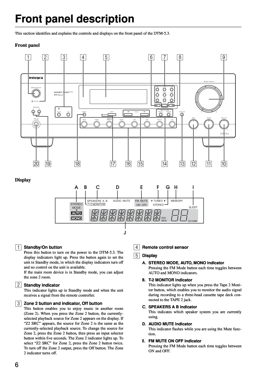
Front panel description, Display, Standby/On button, Standby indicator
Models:
DTM-5.3
1
6
32
32
Download
32 pages
28 Kb
3
4
5
6
7
8
9
10
Troubleshooting
Install
Standby indicator
Connecting components
Preset
Supplied accessories
Direct Tuning button
Setting the ID number
Cleaning all characters
Remote controller description
Page 6
Image 6
Page 5
Page 7
Page 6
Image 6
Page 5
Page 7
Contents
Facilities and connections
Contents
Before using
Setup and operation
Important Safeguards
AVIS
For Canadian model
Precautions
For U.S. model
Modèle pour les Canadien
Features
Supplied accessories
Remote controller description
Facilities and connections
Remote control sensor Display
Standby indicator
Zone 2 button and indicator, Off button
Front panel description
Master Volume dial
Direct Tuning button
Alphabetic letters/symbols buttons
Tuning buttons
A-BUSREADY
Rear panel description
ZONE 2 CONTROL SELECTOR
ZONE 2 OUT
VIDEO IN/OUT
REMOTE CONTROL
Rear panel description
MONITOR OUT
Connecting components
Example of audio equipment connection
Connecting components
Example of video equipment connections
Connecting the speaker cable
Connecting speakers
Connecting the speaker
Connecting a subwoofer
Connecting an FM outdoor antenna
Connecting antennas
Connecting the AM antenna cable
Connecting the included antennas
Connecting the remote zone Zone
Zone 2 connections
Zone 2 Control Selector
from connecting block Mini plug cable
OUT DTM-5.3
DTM-5.3
Connecting the power
Standby indicator Standby/On button
On button Standby button
Installing the remote controller batteries
Installing the batteries
Remote controller operation
Basic operations
Listening to your favorite source
Direct change function
Sleep function Remote controller only
Listening using the headphones
Mute function Remote controller only
Basic operations
Tuning the radio Manual tuning
Tuning the radio Direct tuning
Receiving stations
Receiving stations
Listening to stereo radio stations FM only
Programming radio stations
Preset
Selecting preset stations
Cancelling preset stations
Receiving stations
Entering characters
Cleaning all characters
Entering station names
Changing an entered character
Recording a source
Recording an audio source
Tape-to-Tapedubbing
VCR VIDEO
Recording a source
DTM-5.3
DTM-5.3
Using Tape 2 Monitor
Using a graphic equalizer
Monitoring during recording
Enjoying music in the remote zone
Zone 2 operation from the main room
Zone 2 A-BUSor IR operation in the zone 2 room
Checking the remote controller’s ID
Using the remote controller
Setting the ID number
Programming the ID number
Controlling other components
Controlling an Integra/Onkyo CD player
Controlling an Integra/Onkyo DVD player
Controlling other components
Controlling an Integra/Onkyo cassette tape deck
Trouble
Troubleshooting guide
Appendix
Cause
AMPLIFIER SECTION
REMOTE CONTROLLER RC-477S
Specifications
GENERAL
Top
Page
Image
Contents