Manuals
/
Integra
/
Home Audio
/
Stereo Receiver
Integra
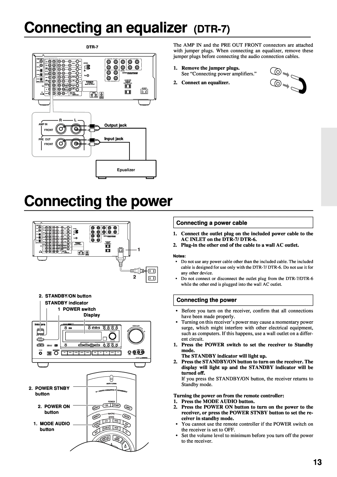
Connecting an equalizer DTR-7, Connecting the power, Connecting a power cable
Models:
DTR-7
1
13
64
64
Download
64 pages
15 Kb
10
11
12
13
14
15
16
17
Troubleshooting
Specs
Install
DSP Digital Signal Processor
indicator
Connecting speakers
Config Setup
Selecting a preset station
Supplied accessories
Screen Setup
Page 13
Image 13
Page 12
Page 14
Page 13
Image 13
Page 12
Page 14
Contents
Preparation
Before using
Operation
Appendix
AVIS
Important Safeguards
1. Warranty Claim
Precautions
5.Power
Note to CATV system installer
Supplied accessories
Features
Key Features
Aluminum volume control
Installing the remote controller batteries
Before operating this unit
Using the remote controller
Do not plug in the power
Audio equipment connections
cord until all connections
have been made
Connections for remote control z
Audio equipment connections
AC outlet connection
Video equipment connections
Connecting equipment with 5.1-channeloutput
Video equipment connections
Decoder with 5.1-channeloutput
Speaker placement
Connecting speakers
FRONT SPEAKERS
Connecting speakers
SURROUND SPEAKERS
CENTER SPEAKER
Connecting speakers
Connecting power amplifiers
Connecting a subwoofer
Connecting power amplifiers
Connecting the power
Connecting an equalizer DTR-7
Connecting a power cable
Connecting the power
Connecting the antenna cable
Making antenna connections
Directional Iinkage
Assembling the AM loop antenna
Connecting the included antennas
Making antenna connections
Connecting an FM outdoor antenna
Connecting an AM outdoor antenna
How to use the on-screendisplay
Using the on-screendisplay
Screen Setup
OSD screens
Using the on-screendisplay
Front
Setting the speaker configuration
Center Surround
Setting the speaker configuration parameters
Using the on-screendisplay
Setting the speaker configuration
Using the on-screendisplay
Setting the speaker distance
Loudspeaker Position Time Synchronization
Center
Setting the speaker Level
Right
R-Sur
Setting the bass peak level
Setting the Speaker level
Bass Peak Level Manager* DTR-7only
Setting the Speaker level
Playing a digital source Digital Input Setup
Using the on-screendisplay
Digital input setup
Tuning in a radio station
Presetting FM/AM radio stations
Cancelling preset stations
Presetting FM/AM radio stations
Programming radio stations
3. Start playing the selected input source
Selecting an input source
Selecting an input source
Selecting an input source
Using the on-screendisplay
Digital Input Setup
Selecting an input source
COAXIAL
Selecting the speaker system
Selecting an input source
Changing the display
Selecting an input source
Adjusting the tone Bass and treble adjustment
Using the on-screendisplay
Selecting a preset station
Setting the MULTI CHANNEL INPUT
Playing a multichannel input source
Using the on-screendisplay
Before Using Listening Mode
Using the Listening Modes
DSP Digital Signal Processor
Listening Modes
3. MASTER VOLUME control knob
Using the listening modes
3. VOLUME buttons
2. Listening mode button
Using the listening modes
Using the listening modes
Input sources and listening modes
Using the listening modes
How to set the listening mode parameters
Setting the listening mode parameters
Using the on-screendisplay
Listening mode parameters
Setting the listening mode parameters
Re-EQCinema Re-Equalization
Late Night
Video Assign Setup
Video Assign Setup
Using the on-screendisplay
PHONO
Giving a name to each input source
Giving a name to each preset radio station
To change a name
To erase a name
To use the above setting from now on
Fine-tuningthe output level of each speaker
1.Press the CH LEVEL button
3.Repeat the operation described in step
Volume display method setup
Other setup operations
IntelliVolume setup
Using the on-screendisplay
movie
Recording a source while listening to music or a
Recording from on audio /video source
Recording a source
Using the on-screendisplay
Recording a source
Adding sound to a video tape
Outline of Multi-roomRemote System
Using Multi-RoomRemote System
Enjoying Music and Movies in the Sub-room
When the system is mounted in a rack
Enjoying Music and Movies in the Sub-room
To control the system in the sub-room
Initial settings
The initial settings
Config Setup
Distance Setup
Using the RC-392Mto control each device
Using the remote controller
Turning the power on and off to the receiver
indicator
Controlling an Onkyo/Integra CD player
Using the remote controller
Controlling an Onkyo/Integra DVD player
Controlling an Onkyo/Integra MD recorder
Using the remote controller
Controlling an Onkyo/Integra tape deck
MODE SAT, CABLE, VCR, and TV buttons
Programming procedure
Erasing a learned code from a MODE button
Erasing a learned code
2 1
Using a Macro function
What is a Macro function?
Programming Macro mode
Macro Direct Learning function
Using a Macro function
Using a Macro function
1.Open the battery cover and remove the batteries
Using a Macro function
3.Press the ENT button
Trouble
Troubleshooting guide
Cause
Remedy
FM/AM
Troubleshooting guide
Video & audio
Others
DTR-7
Specifications
DTR-6
REMOTE CONTROL
Specifications
REMOTE CONTROL
DTR-7
Front panel
Control positions and names
Display
Remote controller
Control positions and names
1 2 3 4 5 6 7 8 9
22 21 20 19
Williams Drive, Ramesy, N.J. 07446, U.S.A
ONKYO U.S.A. CORPORATION
D9907-1
Top
Page
Image
Contents