Hardware
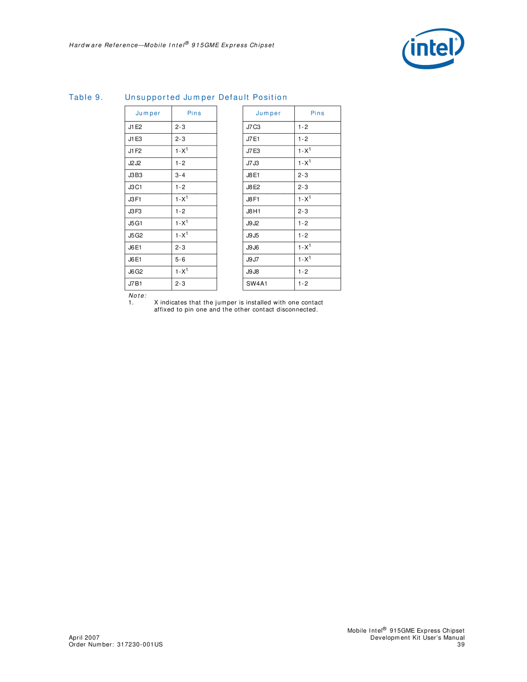
Table 9. Unsupported Jumper Default Position
Jumper | Pins |
| Jumper | Pins |
|
|
|
|
|
J1E2 |
| J7C3 | ||
|
|
|
|
|
J1E3 |
| J7E1 | ||
|
|
|
|
|
J1F2 |
| J7E3 | ||
J2J2 |
| J7J3 | ||
J3B3 |
| J8E1 | ||
|
|
|
|
|
J3C1 |
| J8E2 | ||
|
|
|
|
|
J3F1 |
| J8F1 | ||
J3F3 |
| J8H1 | ||
|
|
|
|
|
J5G1 |
| J9J2 | ||
J5G2 |
| J9J5 | ||
J6E1 |
| J9J6 | ||
J6E1 |
| J9J7 | ||
J6G2 |
| J9J8 | ||
J7B1 |
| SW4A1 | ||
|
|
|
|
|
Note:
1.X indicates that the jumper is installed with one contact affixed to pin one and the other contact disconnected.
| Mobile Intel® 915GME Express Chipset |
April 2007 | Development Kit User’s Manual |
Order Number: | 39 |
