Hardware
into the socket, turn the screw 180 degrees
Caution: Please refer to the CPU installation instruction in Appendix A prior to inserting the CPU as the CPU and socket can be easily damaged.
4.6.2.2PCI Express (x16)
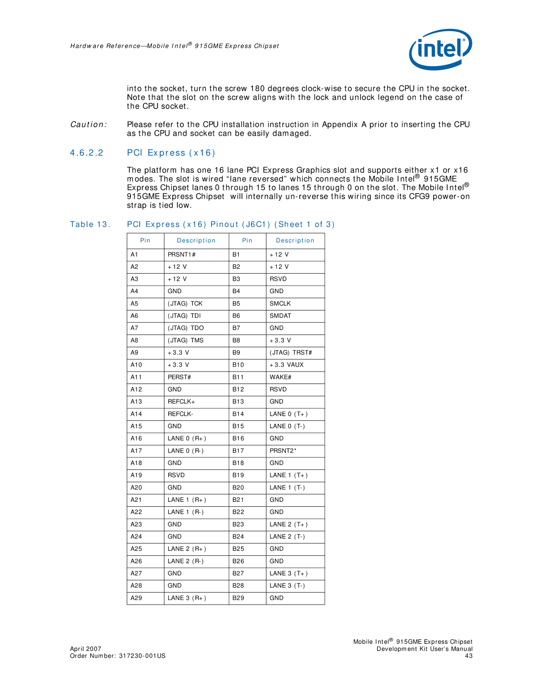
The platform has one 16 lane PCI Express Graphics slot and supports either x1 or x16 modes. The slot is wired “lane reversed” which connects the Mobile Intel® 915GME Express Chipset lanes 0 through 15 to lanes 15 through 0 on the slot. The Mobile Intel® 915GME Express Chipset will internally
Table 13. | PCI Express (x16) Pinout (J6C1) (Sheet 1 of 3) | ||||
|
|
|
|
|
|
| Pin | Description | Pin | Description |
|
|
|
|
|
|
|
| A1 | PRSNT1# | B1 | +12 V |
|
|
|
|
|
|
|
| A2 | +12 V | B2 | +12 V |
|
|
|
|
|
|
|
| A3 | +12 V | B3 | RSVD |
|
|
|
|
|
|
|
| A4 | GND | B4 | GND |
|
|
|
|
|
|
|
| A5 | (JTAG) TCK | B5 | SMCLK |
|
|
|
|
|
|
|
| A6 | (JTAG) TDI | B6 | SMDAT |
|
|
|
|
|
|
|
| A7 | (JTAG) TDO | B7 | GND |
|
|
|
|
|
|
|
| A8 | (JTAG) TMS | B8 | +3.3 V |
|
|
|
|
|
|
|
| A9 | +3.3 V | B9 | (JTAG) TRST# |
|
|
|
|
|
|
|
| A10 | +3.3 V | B10 | +3.3 VAUX |
|
|
|
|
|
|
|
| A11 | PERST# | B11 | WAKE# |
|
|
|
|
|
|
|
| A12 | GND | B12 | RSVD |
|
|
|
|
|
|
|
| A13 | REFCLK+ | B13 | GND |
|
|
|
|
|
|
|
| A14 | REFCLK- | B14 | LANE 0 (T+) |
|
|
|
|
|
|
|
| A15 | GND | B15 | LANE 0 |
|
|
|
|
|
|
|
| A16 | LANE 0 (R+) | B16 | GND |
|
|
|
|
|
|
|
| A17 | LANE 0 | B17 | PRSNT2* |
|
|
|
|
|
|
|
| A18 | GND | B18 | GND |
|
|
|
|
|
|
|
| A19 | RSVD | B19 | LANE 1 (T+) |
|
|
|
|
|
|
|
| A20 | GND | B20 | LANE 1 |
|
|
|
|
|
|
|
| A21 | LANE 1 (R+) | B21 | GND |
|
|
|
|
|
|
|
| A22 | LANE 1 | B22 | GND |
|
|
|
|
|
|
|
| A23 | GND | B23 | LANE 2 (T+) |
|
|
|
|
|
|
|
| A24 | GND | B24 | LANE 2 |
|
|
|
|
|
|
|
| A25 | LANE 2 (R+) | B25 | GND |
|
|
|
|
|
|
|
| A26 | LANE 2 | B26 | GND |
|
|
|
|
|
|
|
| A27 | GND | B27 | LANE 3 (T+) |
|
|
|
|
|
|
|
| A28 | GND | B28 | LANE 3 |
|
|
|
|
|
|
|
| A29 | LANE 3 (R+) | B29 | GND |
|
|
|
|
|
|
|
| Mobile Intel® 915GME Express Chipset |
April 2007 | Development Kit User’s Manual |
Order Number: | 43 |
