Installing and Replacing Desktop Board Components
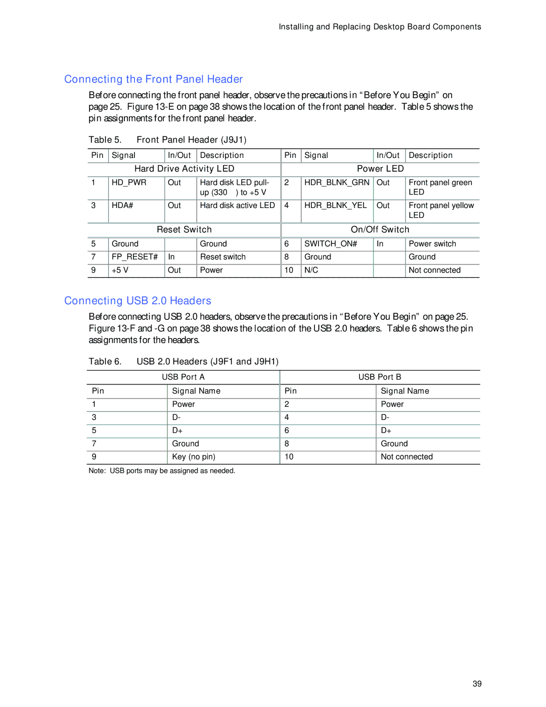
Connecting the Front Panel Header
Before connecting the front panel header, observe the precautions in “Before You Begin” on page 25. Figure
Table 5. Front Panel Header (J9J1)
Pin | Signal | In/Out | Description |
|
|
|
|
| Hard Drive Activity LED | ||
|
|
|
|
1 | HD_PWR | Out | Hard disk LED pull- |
|
|
| up (330 Ω) to +5 V |
|
|
|
|
3 | HDA# | Out | Hard disk active LED |
|
|
|
|
| Reset Switch | ||
|
|
|
|
5 | Ground |
| Ground |
|
|
|
|
7 | FP_RESET# | In | Reset switch |
|
|
|
|
9 | +5 V | Out | Power |
|
|
|
|
Pin | Signal | In/Out | Description |
|
|
|
|
| Power LED |
| |
|
|
|
|
2 | HDR_BLNK_GRN | Out | Front panel green |
|
|
| LED |
|
|
|
|
4 | HDR_BLNK_YEL | Out | Front panel yellow |
|
|
| LED |
|
|
|
|
| On/Off Switch | ||
|
|
|
|
6 | SWITCH_ON# | In | Power switch |
|
|
|
|
8 | Ground |
| Ground |
|
|
|
|
10 | N/C |
| Not connected |
|
|
|
|
Connecting USB 2.0 Headers
Before connecting USB 2.0 headers, observe the precautions in “Before You Begin” on page 25. Figure
Table 6. USB 2.0 Headers (J9F1 and J9H1)
| USB Port A | |
|
|
|
Pin |
| Signal Name |
|
|
|
1 |
| Power |
|
|
|
3 |
| D- |
|
|
|
5 |
| D+ |
|
|
|
7 |
| Ground |
|
|
|
9 |
| Key (no pin) |
|
|
|
| USB Port B | |
|
|
|
Pin |
| Signal Name |
|
|
|
2 |
| Power |
|
|
|
4 |
| D- |
|
|
|
6 |
| D+ |
|
|
|
8 |
| Ground |
|
|
|
10 |
| Not connected |
|
|
|
Note: USB ports may be assigned as needed.
39