Intel Desktop Boards D865GRH Product Guide
Connecting Hardware Control and Power Cables
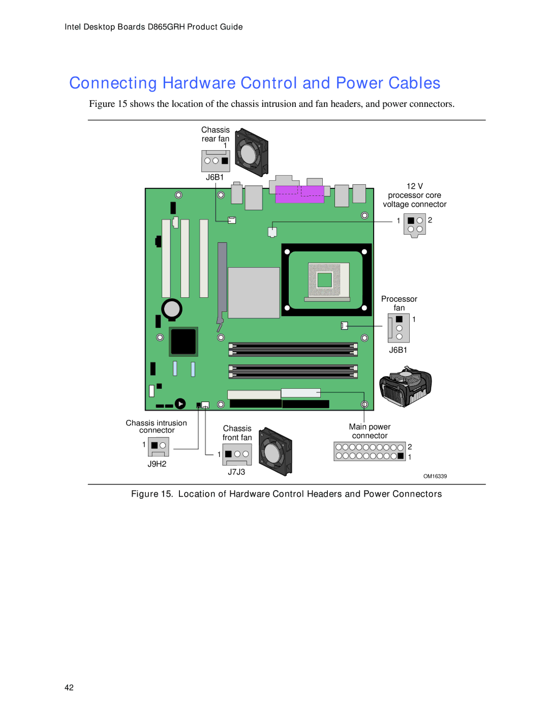
Figure 15 shows the location of the chassis intrusion and fan headers, and power connectors.
| Chassis |
|
|
| rear fan |
|
|
| 1 |
|
|
| J6B1 | 12 V |
|
|
|
| |
|
| processor core | |
|
| voltage connector | |
|
| 1 | 2 |
|
| Processor |
|
|
| fan |
|
|
| 1 |
|
|
| J6B1 |
|
Chassis intrusion | Chassis | Main power |
|
connector |
| ||
1 | front fan | connector |
|
| 2 |
| |
| 1 |
| |
| 1 |
| |
J9H2 |
|
| |
J7J3 |
|
| |
|
| OM16339 | |
|
|
| |
Figure 15. Location of Hardware Control Headers and Power Connectors
42
