INSTALLATIONS
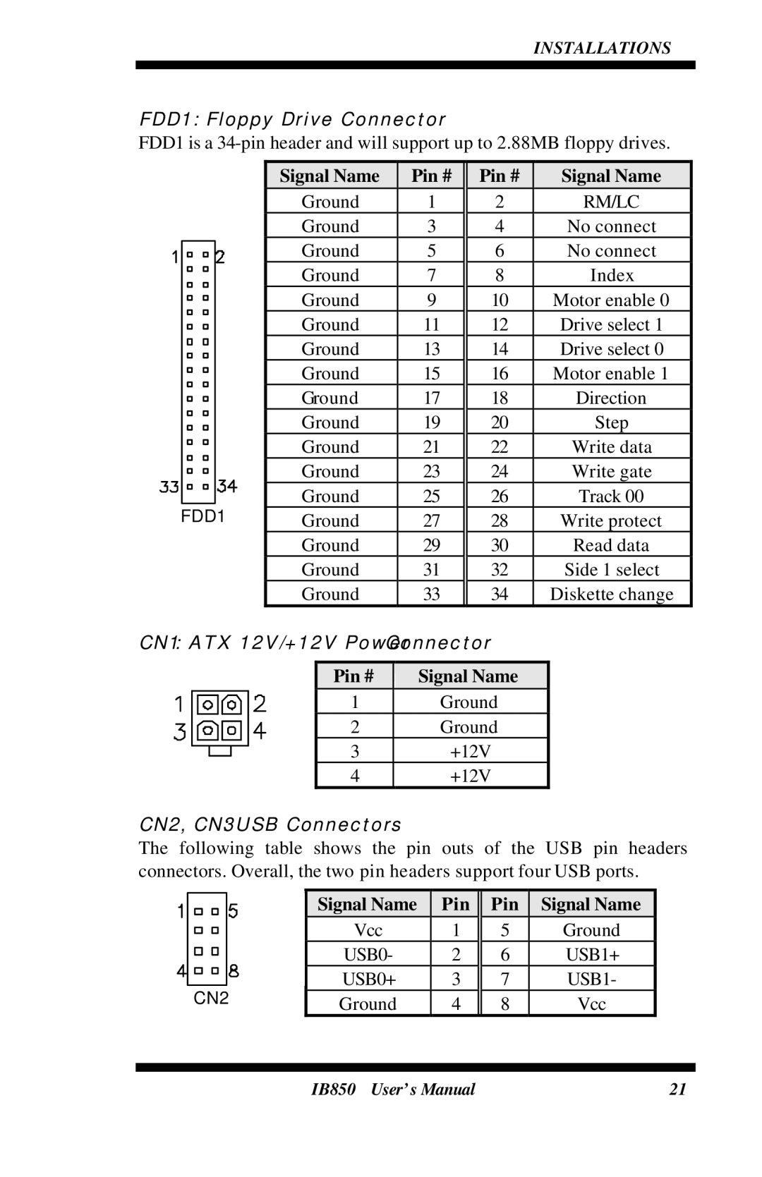
FDD1: Floppy Drive Connector
FDD1 is a
|
|
|
| Signal Name | Pin # | Pin # |
|
| Signal Name |
|
|
|
|
| Ground | 1 | 2 |
|
| RM/LC |
|
|
|
|
| Ground | 3 | 4 |
|
| No connect |
|
|
|
|
| Ground | 5 | 6 |
|
| No connect |
|
|
|
|
|
|
|
| ||||
|
|
|
| Ground | 7 | 8 |
|
| Index |
|
|
|
|
| Ground | 9 | 10 |
|
| Motor enable 0 |
|
|
|
|
| Ground | 11 | 12 |
|
| Drive select 1 |
|
|
|
|
| Ground | 13 | 14 |
|
| Drive select 0 |
|
|
|
|
| Ground | 15 | 16 |
|
| Motor enable 1 |
|
|
|
|
| Ground | 17 | 18 |
|
| Direction |
|
|
|
|
| Ground | 19 | 20 |
|
| Step |
|
|
|
|
| Ground | 21 | 22 |
|
| Write data |
|
|
|
|
| Ground | 23 | 24 |
|
| Write gate |
|
|
|
|
| Ground | 25 | 26 |
|
| Track 00 |
|
|
|
|
|
|
|
| ||||
FDD1 |
|
|
|
|
|
|
|
| ||
| Ground | 27 | 28 |
|
| Write protect |
| |||
|
|
|
| Ground | 29 | 30 |
|
| Read data |
|
|
|
|
| Ground | 31 | 32 |
|
| Side 1 select |
|
|
|
|
| Ground | 33 | 34 |
|
| Diskette change |
|
CN1: ATX 12V/+12V Power Connector
Pin # | Signal Name |
1 | Ground |
2 | Ground |
3 | +12V |
4 | +12V |
CN2, CN3: USB Connectors
The following table shows the pin outs of the USB pin headers connectors. Overall, the two pin headers support four USB ports.
|
|
|
|
| Signal Name |
|
| Pin |
|
| Pin |
|
| Signal Name |
|
|
|
|
|
| Vcc |
| 1 |
| 5 |
|
| Ground |
| ||
|
|
|
|
| USB0- |
| 2 |
| 6 |
|
| USB1+ |
| ||
|
|
|
|
| USB0+ |
| 3 |
| 7 |
|
| USB1- |
| ||
|
|
|
|
|
|
|
| ||||||||
|
| CN2 |
|
|
|
|
|
|
|
|
|
| |||
|
|
| Ground |
| 4 |
| 8 |
|
| Vcc |
| ||||
IB850 User’s Manual | 21 |