INSTALLATIONS
J1: System Function Connector
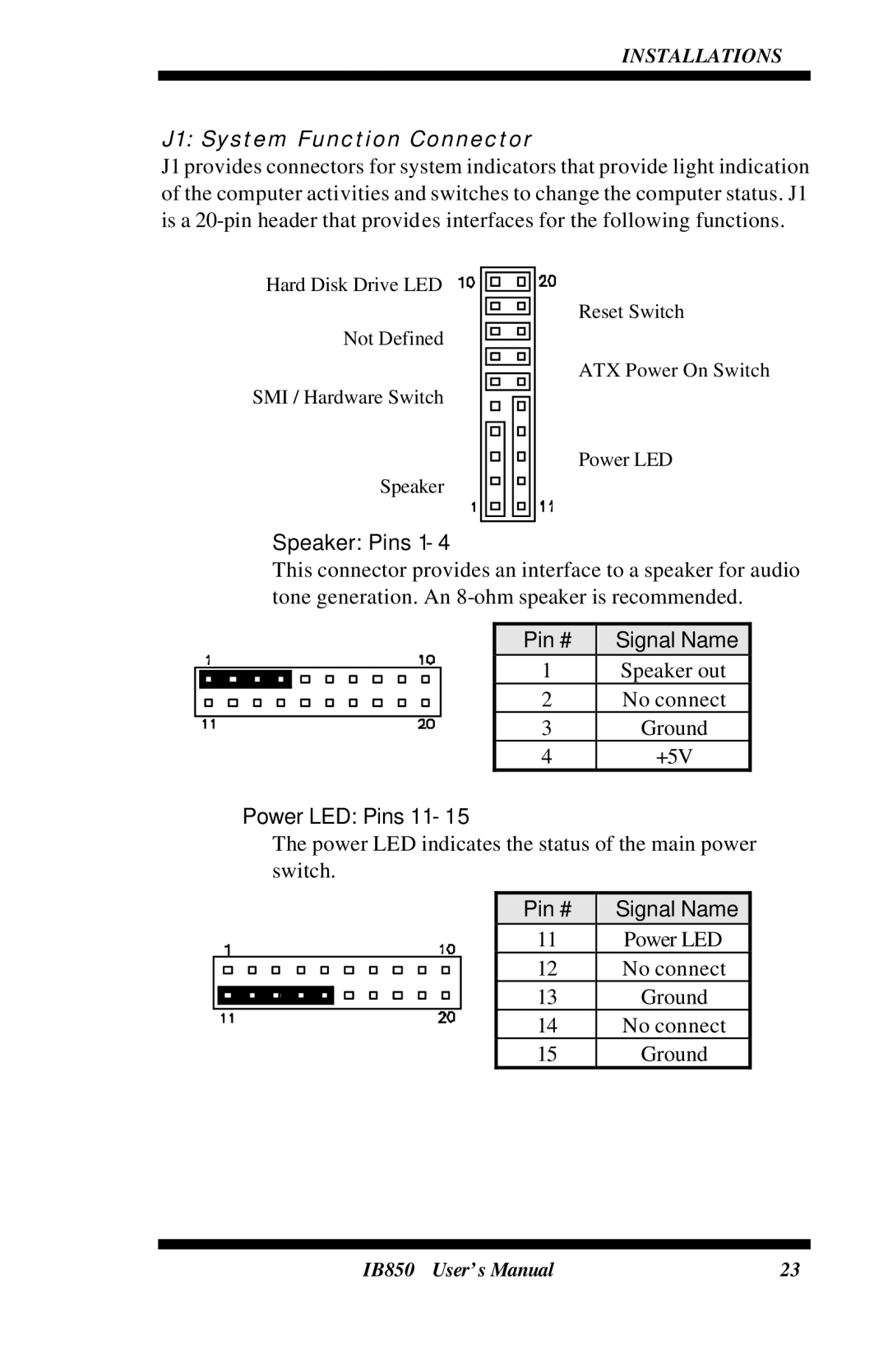
J1 provides connectors for system indicators that provide light indication of the computer activities and switches to change the computer status. J1 is a
Hard Disk Drive LED
Not Defined
SMI / Hardware Switch
Speaker
Reset Switch
ATX Power On Switch
Power LED
Speaker: Pins 1 - 4
This connector provides an interface to a speaker for audio tone generation. An
Pin # | Signal Name |
1 | Speaker out |
2 | No connect |
3 | Ground |
4 | +5V |
Power LED: Pins 11 - 15
The power LED indicates the status of the main power switch.
Pin # | Signal Name |
11 | Power LED |
12 | No connect |
13 | Ground |
14 | No connect |
15 | Ground |
IB850 User’s Manual | 23 |