Hardware Setup
Keyboard Connector
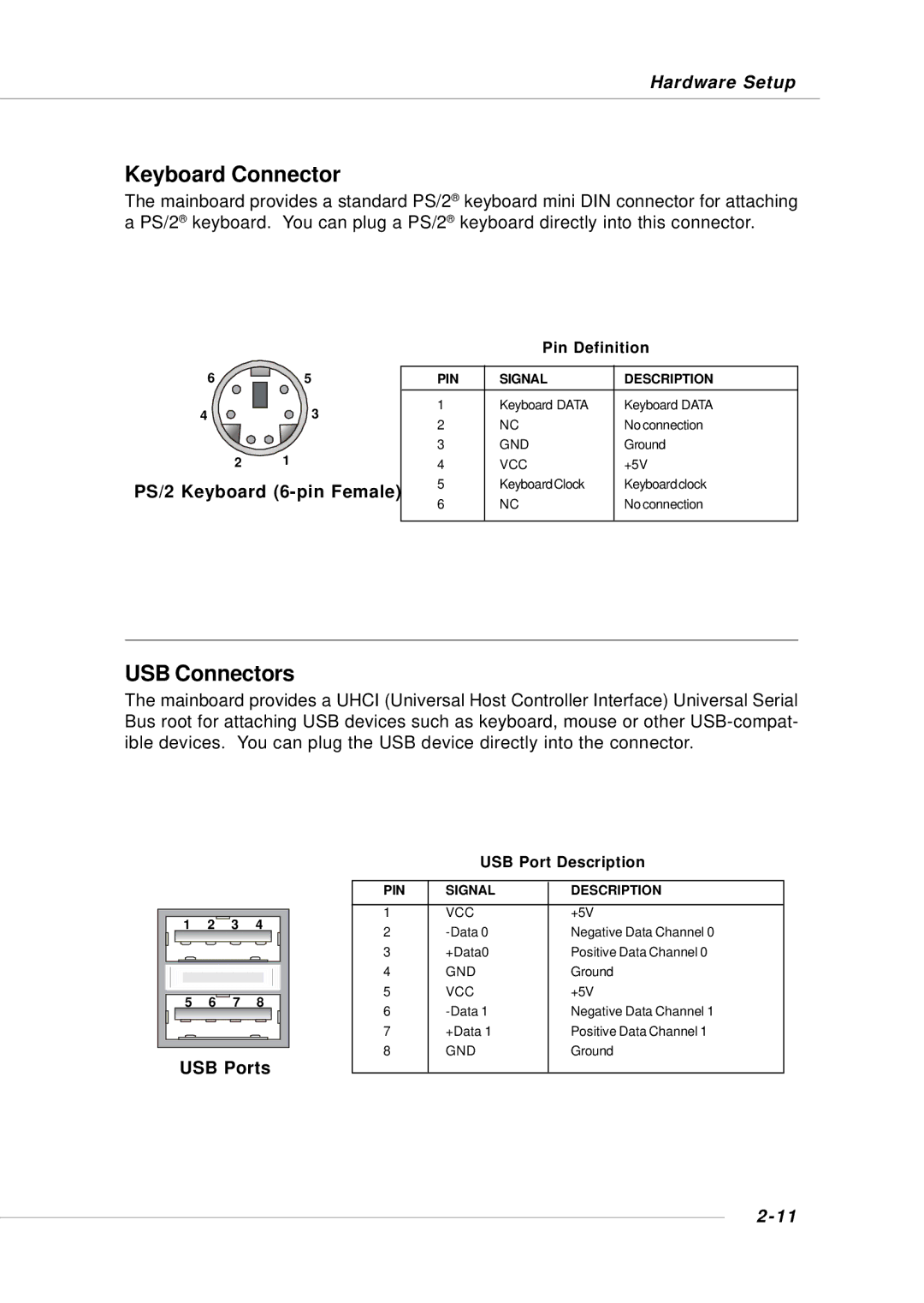
The mainboard provides a standard PS/2® keyboard mini DIN connector for attaching a PS/2® keyboard. You can plug a PS/2® keyboard directly into this connector.
Pin Definition
6 ![]()
![]()
![]()
![]()
![]()
![]()
![]()
![]()
![]()
![]()
![]()
![]() 5
5
4 | 3 |
2 1
PS/2 Keyboard (6-pin Female)
PIN | SIGNAL | DESCRIPTION |
1 | Keyboard DATA | Keyboard DATA |
2 | NC | No connection |
3 | GND | Ground |
4 | VCC | +5V |
5 | KeyboardClock | Keyboardclock |
6 | NC | No connection |
|
|
|
USB Connectors
The mainboard provides a UHCI (Universal Host Controller Interface) Universal Serial Bus root for attaching USB devices such as keyboard, mouse or other
1 | 2 | 3 | 4 |
5 | 6 | 7 | 8 |
USB Ports
USB Port Description
PIN | SIGNAL | DESCRIPTION |
|
|
|
1 | VCC | +5V |
2 | Negative Data Channel 0 | |
3 | +Data0 | Positive Data Channel 0 |
4 | GND | Ground |
5 | VCC | +5V |
6 | Negative Data Channel 1 | |
7 | +Data 1 | Positive Data Channel 1 |
8 | GND | Ground |
|
|
|