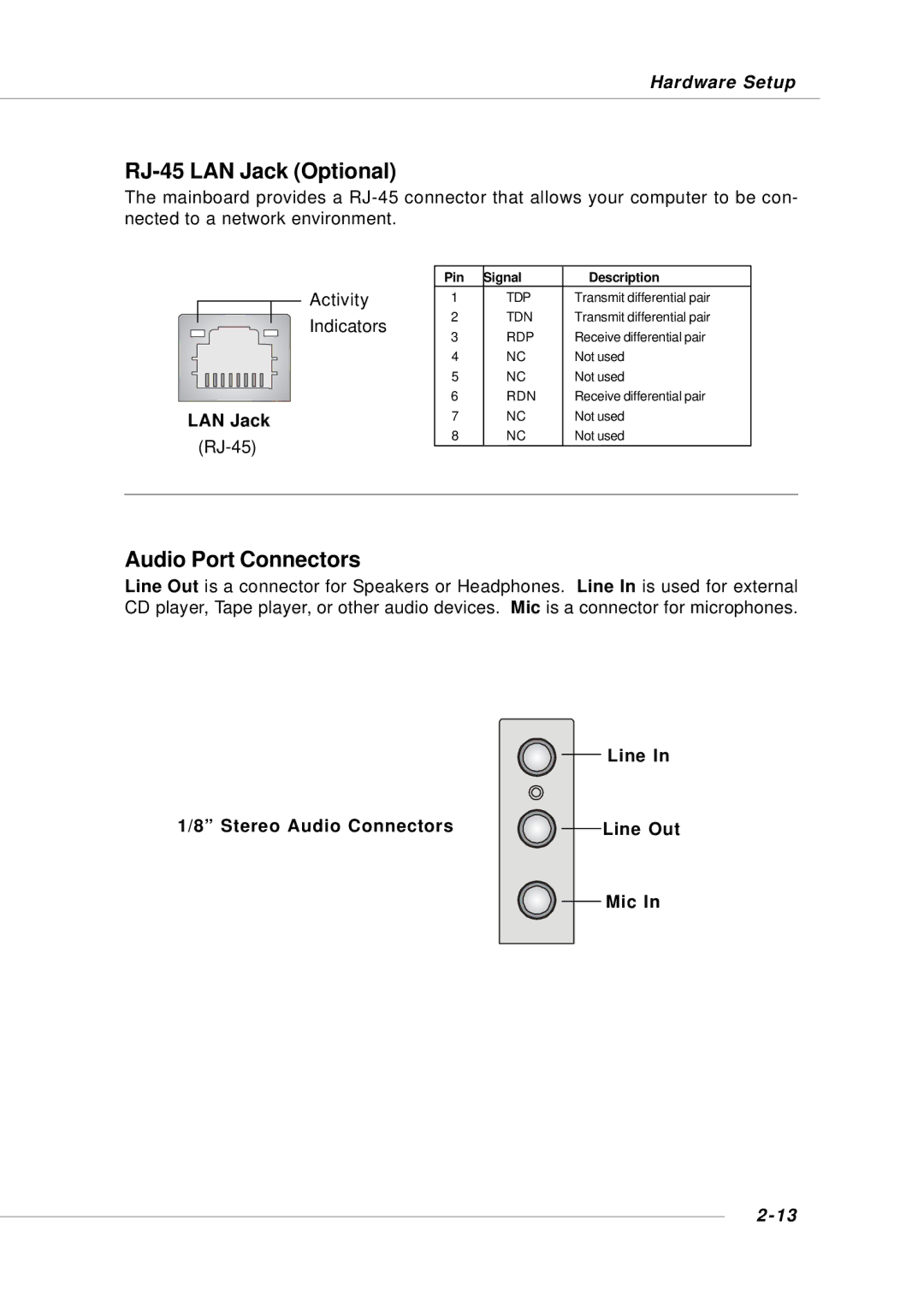
G52-M6734XD
KM4M/KM4AM Series
MS-6734 v1.X M-ATX Mainboard
FCC-B Radio Frequency Interference Statement
VOIR LA NOTICE D’INSTALLATION AVANT DE RACCORDER AU RESEAU
Micro-Star International MS-6734
Revision
Copyright Notice
Trademarks
Revision History
Technical Support
Safety Instructions
Chapter 1. Getting Started
CONTENTS
Chapter 2. Hardware Setup
Chapter 4. VIA VT8237 Serial ATA RAID Introduction
Chapter 3. BIOS Setup
Getting Started
Main Memory
Mainboard Specifications
MS-6734 M-ATX Mainboard
Chipset
Audio
BIOS
Dimension
Getting Started
MS-6734 M-ATX Mainboard
Mainboard Layout
MS-6734 v1.X M-ATX Mainboard
BIOS
Hardware Setup
JPW1, p.2-9
Quick Components Guide
MS-6734 M-ATX Mainboard
Back Panel I/O, p.2-10
Central Processing Unit CPU
WARNING! Thermal Issue for CPU
CPU Core Speed Derivation Procedure
Hardware Setup
MS-6734 M-ATX Mainboard
CPU Installation Procedures for Socket
unplug the power cord before
installing the CPU
Hardware Setup
Installing AMD Athlon CPU Socket 462 Cooler Set
MSI Reminds You
Overclocking
CPU Clock Frequency Selection through BIOS
Overheating
Replacing the CPU
Hardware Setup
Memory
Memory Speed/CPU FSB Support Matrix
DDR DIMM Slots DIMM1
D Double Side
Installing DDR Modules
DIMM Module Combination
S Single Side
CONN1
Power Supply
ATX 20-Pin Power Connector CONN1
ATX 12V Power Connector JPW1
IEEE1394
Mouse Connector
Back Panel
Mouse
USB Ports
Keyboard Connector
USB Connectors
PS/2 Keyboard 6-pin Female
IEEE1394 Port Optional
Serial Port Connector COM
VGA Connector
9-Pin Male DIN Connector
LAN Jack
Audio Port Connectors
1/8” Stereo Audio Connectors
RJ-45 LAN Jack Optional
MS-6734 M-ATX Mainboard
Parallel Port Connector LPT1
2-14
SIGNAL
FDD1
Connectors
Floppy Disk Drive Connector FDD1
Fan Power Connectors CPUFA1/SYSFA1
MS-6734 M-ATX Mainboard
Hard Disk Connectors IDE1 & IDE2
IDE1 IDE2
2-16
Hardware Setup
SATA1
SATA2
2-17
JFP1
Front Panel Connectors JFP1 & JFP2
CD-In Connector JCD1
JFP2
2-19
Front USB Connectors JUSB2 & JUSB3 JUSB3 is optional
JUSB2 JUSB3 Optional
USB 2.0 Bracket
2-20
IEEE 1394 Connectors J13941 & J13942 Optional
J13941 / J13942 Optional
IEEE1394 Bracket Optional
JSP1
Front Panel Audio Connector JAUD1
SPDIF-Out Connector JSP1
JAUD1
JBAT1
Jumpers
Clear CMOS Jumper JBAT1
CPU Frequency Jumpers SW1 & SW2
PCI Interrupt Request Routing
Slots
AGP Accelerated Graphics Port Slot
PCI Peripheral Component Interconnect Slots
MSI Reminds You
BIOS Setup
091096 refers to the date this BIOS is released
example W7005MS V2.0 091096 where
Main Menu
Entering Setup
Control Keys
Getting Help
Advanced Chipset Features
BIOS Setup
Standard CMOS Features
Advanced BIOS Features
Set User Password
Load Fail-Safe Defaults
Load Optimized Defaults
Set Supervisor Password
date
Standard CMOS Features
Time
month
The system stops when any error is detected
Access Mode
The settings are CHS, LBA, Large, Auto
All Errors
1st/2nd/3rd Boot Device
Advanced BIOS Features
Quick Boot
Boot Sequence
Setup
Settings Disabled, Enabled
Boot Up NumLock Status
Typematic Rate Setting
BIOS Setup
APIC Mode
MPS Table Version
HDD S.M.A.R.T. Capability
Current FSB / DRAM / DDR Frequency
Advanced Chipset Features
Change these settings only if you are familiar with the chipset
DRAM Clock/Drive Control
Precharge To Active Trp
DRAM Command Rate
DRAM CAS Latency
Bank Interleave
AGP Driving Control
AGP & P2P Bridge Control
AGP Aperture Size
AGP Mode
VIA OnChip IDE Device
IDE DMA Transfer Access
Integrated Peripherals
Onboard 1394 Chip
VIA OnChip PCI Device
Onboard Lan Boot ROM
Primary/Secondary Master/Slave PIO
Primary/Secondary Master/Slave UltraDMA
Onboard FDC Controller
Disabled
USB Legacy Keyboard/MS Support
Super IO Device
MS-6734 M-ATX Mainboard
ECP Mode Use DMA
Init Display First
3-16
Sleep State
Power Management Setup
Power Management Option
IPCA Function
After AC Power Lost
HDD Power Down
Power Button Function
Run VGABIOS if S3 Resume
PS2MS Wake Up from S3/S4/S5
Resume By Alarm
PS2KB Wakeup Select
PS2KB Wake Up from S3/S4/S5
Primary INTR
Dateof Month Alarm
Timehhmmss Alarm
IRQ Activity Monitoring
IRQ Resources
PNP/PCI Configurations
Clear ESCD
Resource Controlled By
VGA Palette Snoop
Bit Setting
Enabled
PCI/VGA Palette Snoop
3-23
PC Health Status
CPU Warning Temperature
Shutdown Temperature
3-24
Frequency/Voltage Control
Auto Detect DIMM/PCI Clk
Spread Spectrum
BIOS Setup
Load Fail-Safe/Optimized Defaults
3-25
MS-6734 M-ATX Mainboard
Set Supervisor/User Password
About Supervisor Password & User Password
3-26
Introduction
VIA VT8237 Serial ATA RAID Introduction
VIA VT8237 Serial ATA RAID Appendix. Using 4- or 6-Channel
Audio Function
RAID 1 Mirroring
Introduction
RAID Basics
RAID 0 Striping
VIA VT8237 Serial ATA RAID Introduction
BIOS Configuration
MSI Reminds You
Create Disk Array
MS-6734 M-ATX Mainboard
VIA VT8237 Serial ATA RAID Introduction
After array mode is selected, there are two methods to create a disk array. One method is “Auto Setup” and the other one is “Select Disk Drives”. Auto Setup allows BIOS to select the disk drives and create arrays automatically, but it does not duplicate the mirroring drives even if the user selected Create and duplicate for RAID 1. It is recommended all disk drives are new ones when wanting to create an array. Select Disk Drives lets the user select the array drives by their requirements. When using Select Disk Drives, the channel column will be activated. Highlight the target drives that you want to use and press Enter to select them. After all drives have been selected, press Esc to go back to the creation steps menu
8KB For specialized usage models requiring 8KB blocks
64KB Optimal setting
Delete Disk Array
4KB For specialized usage models requiring 4KB blocks
VIA VT8237 Serial ATA RAID Introduction
Create and Delete Spare Hard Drive
View Serial Number of Hard Drive
MS-6734 M-ATX Mainboard
Duplicate Critical RAID 1 Array
Rebuild Broken RAID 1 Array
2. Destroy the Mirroring Relationship
1. Power off and Check the Failed Drive
3. Choose Replacement Drive and Rebuild
4. Continue to boot
h Existing Windows XP Driver Installation
Installing RAID Software & Drivers
Install Driver in Windows OS
h New Windows OS 2000/XP/NT4 Installation
VIA VT8237 Serial ATA RAID Introduction
Installation of VIA SATA RAID Utility
4-11
MS-6734 M-ATX Mainboard
4-12
VIA VT8237 Serial ATA RAID Introduction
Using VIA RAID Tool
4-13
Click on o r button to determine the viewing type of left window pane. There are two viewing types By controllers and by device. Click on the object in the left window pane to display the status of the object in the right windowpane. The following screen shows the status of Array 0---RAID
4-14
MS-6734 M-ATX Mainboard
button to view the statuses of Array
4-15
VIA VT8237 Serial ATA RAID Introduction
You may also use the same