BIOS Setup
The Main Menu
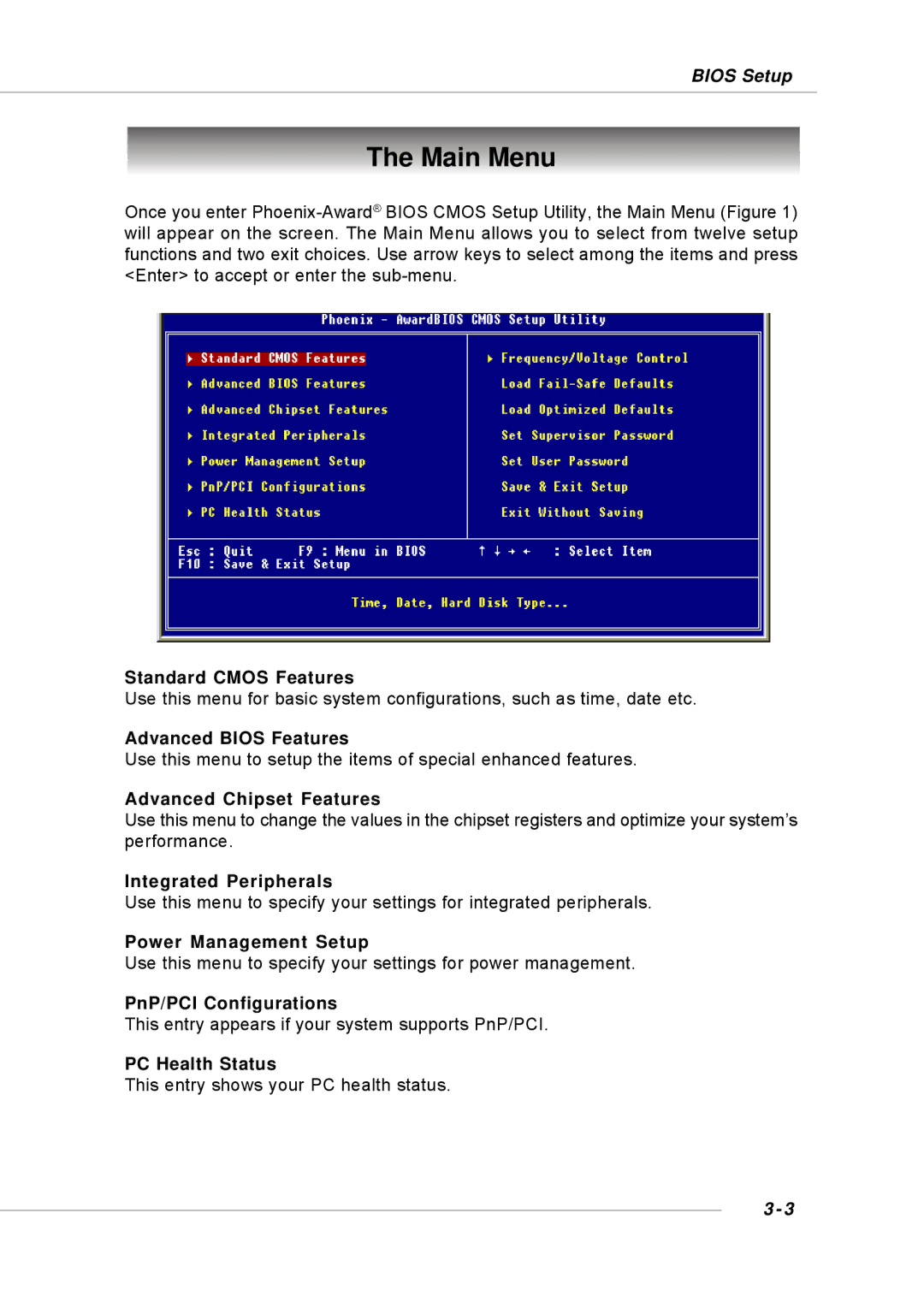
Once you enter
Standard CMOS Features
Use this menu for basic system configurations, such as time, date etc.
Advanced BIOS Features
Use this menu to setup the items of special enhanced features.
Advanced Chipset Features
Use this menu to change the values in the chipset registers and optimize your system’s performance.
Integrated Peripherals
Use this menu to specify your settings for integrated peripherals.
Power Management Setup
Use this menu to specify your settings for power management.
PnP/PCI Configurations
This entry appears if your system supports PnP/PCI.
PC Health Status
This entry shows your PC health status.
3 - 3