SECTION
SECTION 4—FRONT RIGGINGS
WARNING
After any adjustments, repair or service and before use, make sure all attaching hardware is tightened securely. Otherwise injury or damage may occur.
Installing/Removing Front Riggings
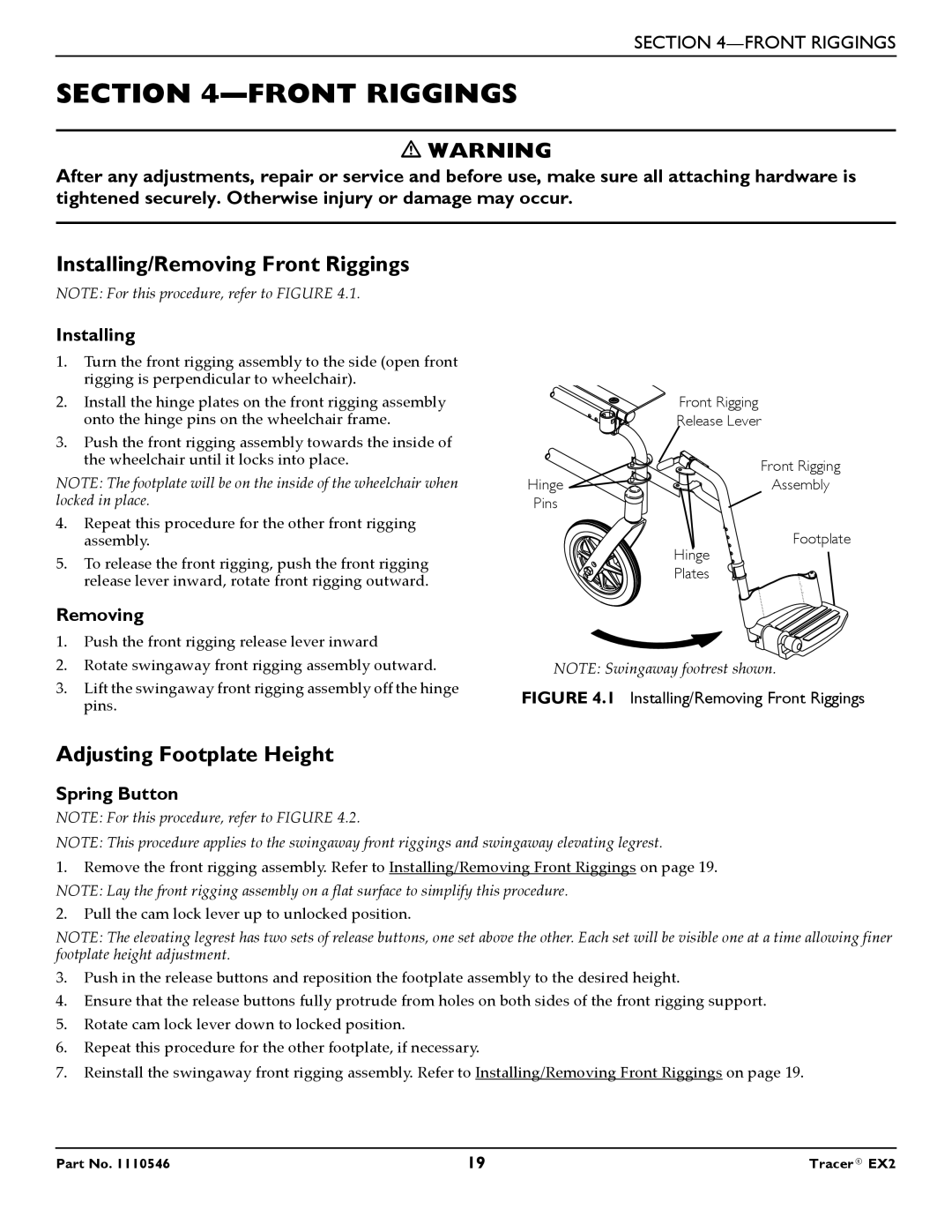
NOTE: For this procedure, refer to FIGURE 4.1.
Installing
1.Turn the front rigging assembly to the side (open front rigging is perpendicular to wheelchair).
2.Install the hinge plates on the front rigging assembly onto the hinge pins on the wheelchair frame.
3.Push the front rigging assembly towards the inside of the wheelchair until it locks into place.
NOTE: The footplate will be on the inside of the wheelchair when locked in place.
4.Repeat this procedure for the other front rigging assembly.
5.To release the front rigging, push the front rigging release lever inward, rotate front rigging outward.
Removing
1.Push the front rigging release lever inward
2.Rotate swingaway front rigging assembly outward.
3.Lift the swingaway front rigging assembly off the hinge pins.
| Front Rigging |
| Release Lever |
| Front Rigging |
Hinge | Assembly |
Pins |
|
| Footplate |
| Hinge |
| Plates |
NOTE: Swingaway footrest shown.
FIGURE 4.1 Installing/Removing Front Riggings
Adjusting Footplate Height
Spring Button
NOTE: For this procedure, refer to FIGURE 4.2.
NOTE: This procedure applies to the swingaway front riggings and swingaway elevating legrest.
1.Remove the front rigging assembly. Refer to Installing/Removing Front Riggings on page 19. NOTE: Lay the front rigging assembly on a flat surface to simplify this procedure.
2.Pull the cam lock lever up to unlocked position.
NOTE: The elevating legrest has two sets of release buttons, one set above the other. Each set will be visible one at a time allowing finer footplate height adjustment.
3.Push in the release buttons and reposition the footplate assembly to the desired height.
4.Ensure that the release buttons fully protrude from holes on both sides of the front rigging support.
5.Rotate cam lock lever down to locked position.
6.Repeat this procedure for the other footplate, if necessary.
7.Reinstall the swingaway front rigging assembly. Refer to Installing/Removing Front Riggings on page 19.
Part No. 1110546 | 19 | Tracer® EX2 |