PROCEDURE 1 | FOOTREST |
|
|
F O O T R E S T
This Procedure includes the following:
Installing/Removing Footrest(s) Adjusting Footrest Height
Installing Adjustable
Installing/Adjusting Adjustable Angle
Impact Guards/Calf Strap Replacing Heel Loops Installing/Removing Elevating Legrests
Raising/Lowering Elevating Legrests and/or Adjusting Calfpads
Installing Basketball Roller
WARNING
After adjustments and BEFORE use, make sure all attaching hardware is securely tightened, otherwise injury or damage may occur.
NOTE: The following procedures are for
INSTALLING/REMOVING
FOOTREST(S) (FIGURE 1)
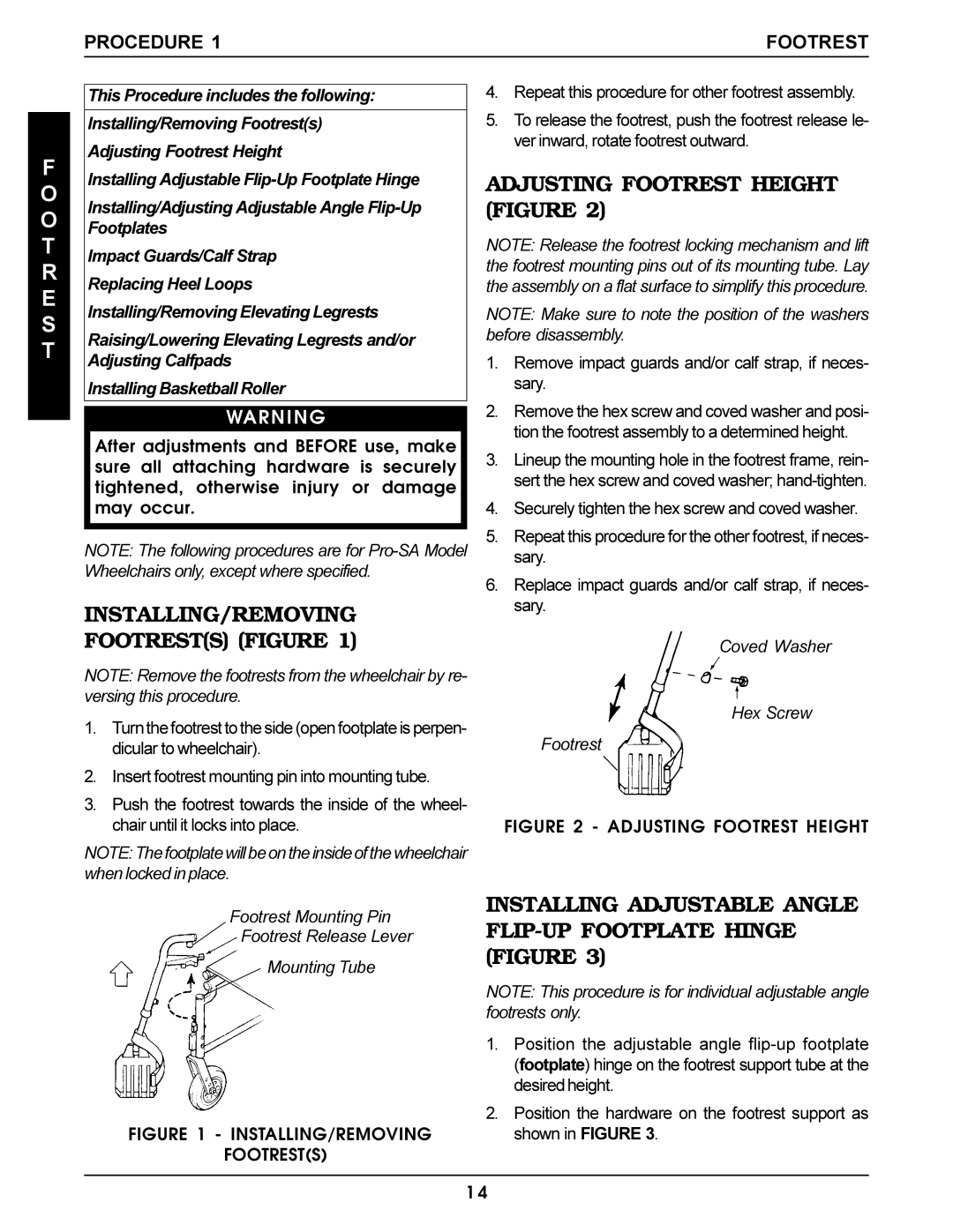
NOTE: Remove the footrests from the wheelchair by re- versing this procedure.
1.Turn the footrest to the side (open footplate is perpen- dicular to wheelchair).
2.Insert footrest mounting pin into mounting tube.
3.Push the footrest towards the inside of the wheel- chair until it locks into place.
NOTE: The footplate will be on the inside of the wheelchair when locked in place.
Footrest Mounting Pin
Footrest Release Lever
Mounting Tube
FIGURE 1 - INSTALLING/REMOVING
FOOTREST(S)
4.Repeat this procedure for other footrest assembly.
5.To release the footrest, push the footrest release le- ver inward, rotate footrest outward.
ADJUSTING FOOTREST HEIGHT (FIGURE 2)
NOTE: Release the footrest locking mechanism and lift the footrest mounting pins out of its mounting tube. Lay the assembly on a flat surface to simplify this procedure.
NOTE: Make sure to note the position of the washers before disassembly.
1.Remove impact guards and/or calf strap, if neces- sary.
2.Remove the hex screw and coved washer and posi- tion the footrest assembly to a determined height.
3.Lineup the mounting hole in the footrest frame, rein- sert the hex screw and coved washer;
4.Securely tighten the hex screw and coved washer.
5.Repeat this procedure for the other footrest, if neces- sary.
6.Replace impact guards and/or calf strap, if neces- sary.
Coved Washer
Hex Screw
Footrest
FIGURE 2 - ADJUSTING FOOTREST HEIGHT
INSTALLING ADJUSTABLE ANGLE FLIP-UP FOOTPLATE HINGE (FIGURE 3)
NOTE: This procedure is for individual adjustable angle footrests only.
1.Position the adjustable angle
2.Position the hardware on the footrest support as shown in FIGURE 3.
1 4