ARMS |
|
| PROCEDURE 4 | |
|
|
| ||
|
|
| Lever - Unlocked | |
|
|
| Position | |
|
|
| ||
|
| Set | Inside | |
|
| Screws | Post | |
Wheelchair |
| Outside T- |
| |
| arm Post |
| ||
Frame | Locking Lever |
| ||
|
| |||
|
|
| ||
| (Towards the |
| ||
front of the |
| Locked Position | ||
wheelchair.) | FIGURE 4 - ADJUSTING THE | |||
Socket | ||||
| ||||
| Slot |
| HEIGHT | |
|
|
| ||
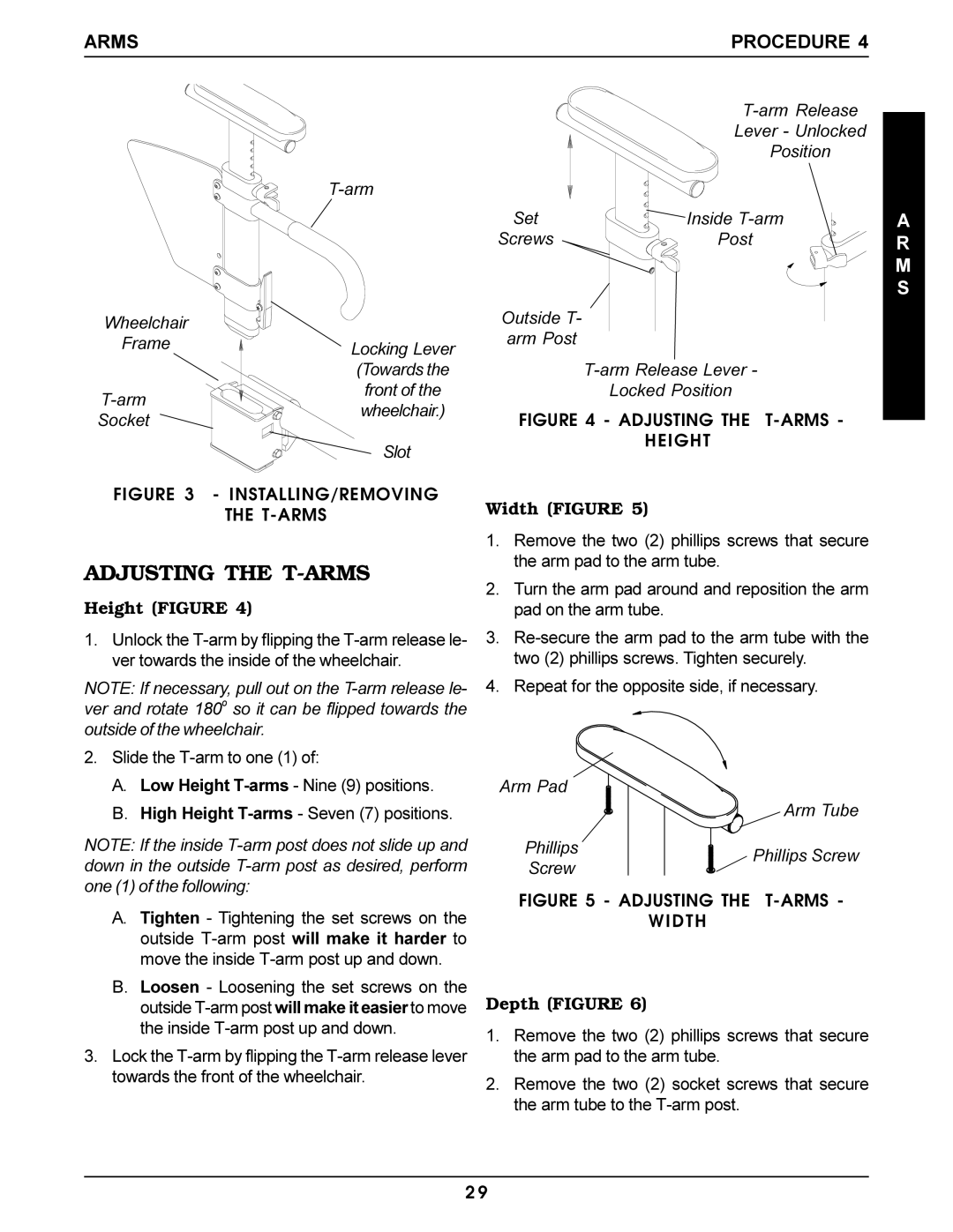
FIGURE 3 | - INSTALLING/REMOVING |
|
| |
THE | Width (FIGURE 5) | ||
|
| ||
| 1. | Remove the two (2) phillips screws that secure | |
ADJUSTING THE |
| the arm pad to the arm tube. | |
2. | Turn the arm pad around and reposition the arm | ||
Height (FIGURE 4) | |||
| pad on the arm tube. | ||
1. Unlock the | 3. | ||
ver towards the inside of the wheelchair. |
| two (2) phillips screws. Tighten securely. | |
NOTE: If necessary, pull out on the | 4. | Repeat for the opposite side, if necessary. | |
ver and rotate 180o so it can be flipped towards the |
|
| |
outside of the wheelchair. |
|
| |
2. Slide the
A. | Low Height | Arm Pad |
| |
B. | High Height |
| Arm Tube | |
NOTE: If the inside | Phillips | Phillips Screw | ||
down in the outside | Screw | |||
| ||||
one (1) of the following: | FIGURE 5 - ADJUSTING THE | |||
A. | Tighten - Tightening the set screws on the | |||
WIDTH |
| |||
| outside |
|
| |
| move the inside |
|
| |
B. Loosen - Loosening the set screws on the | Depth (FIGURE 6) |
| ||
| outside |
| ||
| the inside | 1. Remove the two (2) phillips screws that secure | ||
|
| |||
3. Lock the | the arm pad to the arm tube. |
| ||
towards the front of the wheelchair. | 2. Remove the two (2) socket screws that secure | |||
|
| |||
the arm tube to the
A R M S
2 9
