R
PROCEDURE 6 | REAR WHEELS | |
|
| |
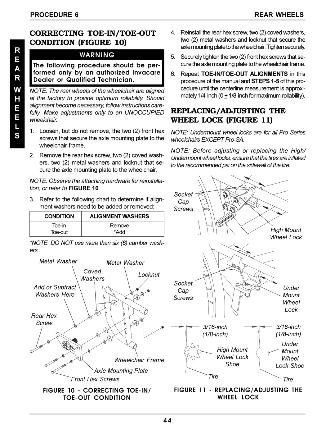
CORRECTING | 4. Reinstall the rear hex screw, two (2) coved washers, | |
CONDITION (FIGURE 10) | two (2) metal washers and locknut that secure the | |
axlemountingplatetothewheelchair.Tightensecurely. | ||
|
E
A
R
W H E E L S
WARNING
The following procedure should be per- formed only by an authorized Invacare Dealer or Qualified Technician.
NOTE: The rear wheels of the wheelchair are aligned at the factory to provide optimum rollability. Should alignment become necessary, follow instructions care- fully. Make adjustments only to an UNOCCUPIED wheelchair.
1.Loosen, but do not remove, the two (2) front hex screws that secure the axle mounting plate to the wheelchair frame.
2.Remove the rear hex screw, two (2) coved wash- ers, two (2) metal washers and locknut that se- cure the axle mounting plate to the wheelchair.
NOTE: Observe the attaching hardware for reinstalla- tion, or refer to FIGURE 10.
3.Refer to the following chart to determine if align- ment washers need to be added or removed:
CONDITION | ALIGNMENT WASHERS |
|
|
Remove | |
*Add | |
|
|
*NOTE: DO NOT use more than six (6) camber wash- ers.
Metal Washer | Metal Washer |
CovedLocknut Washers
Add or Subtract Washers Here
Rear Hex
Screw
Wheelchair Frame
Axle Mounting Plate
Front Hex Screws
FIGURE 10 - CORRECTING TOE-IN/
TOE-OUT CONDITION
5.Securely tighten the two (2) front hex screws that se- cure the axle mounting plate to the wheelchair frame.
6.Repeat
REPLACING/ADJUSTING THE WHEEL LOCK (FIGURE 11)
NOTE: Undermount wheel locks are for all Pro Series wheelchairs EXCEPT
NOTE: Before adjusting or replacing the High/ Undermount wheel locks, ensure that the tires are inflated to the recommended psi on the sidewall of the tire.
Socket
Cap
Screws
High Mount
Wheel Lock
Socket | Under | |
Cap | ||
Mount | ||
Screws | ||
Wheel | ||
| ||
| Lock | |
High Mount | Under | |
Mount | ||
Wheel Lock | Wheel | |
Shoe | Lock Shoe | |
Tire | Tire | |
|
FIGURE 11 - REPLACING/ADJUSTING THE
WHEEL LOCK
4 4