FRONT RIGGINGS | PROCEDURE 1 |
|
|
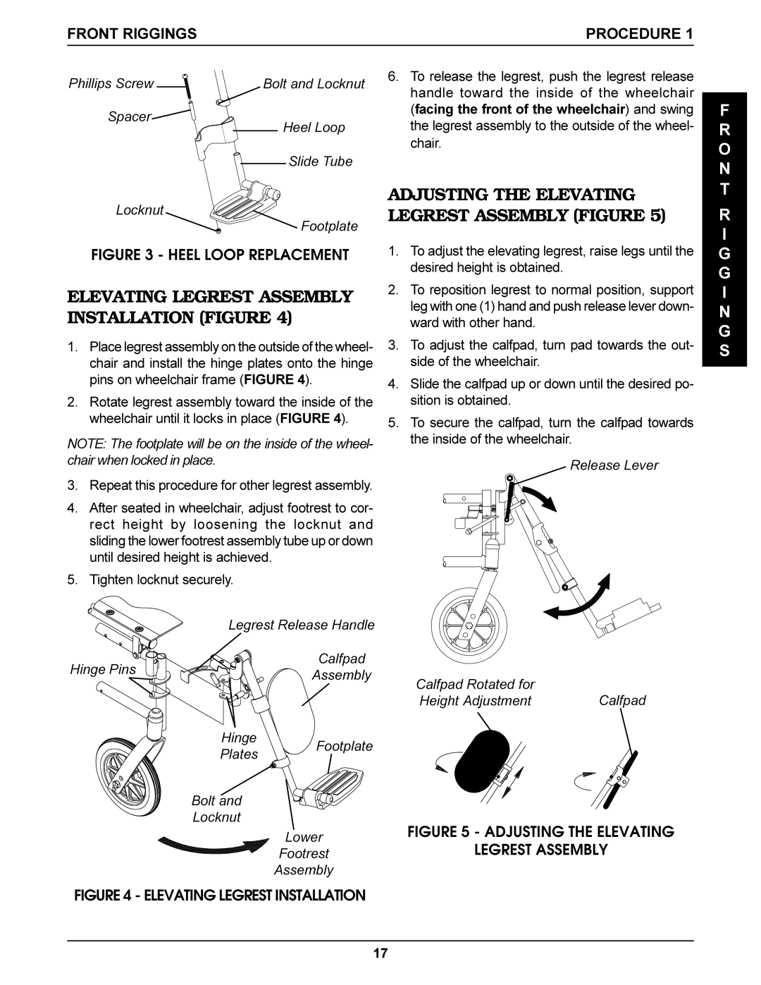
Phillips Screw | Bolt and Locknut |
Spacer
Heel Loop
Slide Tube
Locknut
Footplate
FIGURE 3 - HEEL LOOP REPLACEMENT
ELEVATING LEGREST ASSEMBLY INSTALLATION (FIGURE 4)
1.Place legrest assembly on the outside of the wheel- chair and install the hinge plates onto the hinge pins on wheelchair frame (FIGURE 4).
2.Rotate legrest assembly toward the inside of the wheelchair until it locks in place (FIGURE 4).
NOTE: The footplate will be on the inside of the wheel- chair when locked in place.
3.Repeat this procedure for other legrest assembly.
4.After seated in wheelchair, adjust footrest to cor- rect height by loosening the locknut and sliding the lower footrest assembly tube up or down until desired height is achieved.
5.Tighten locknut securely.
| Legrest Release Handle | |
Hinge Pins | Calfpad | |
Assembly | ||
|
Hinge Footplate
Plates
Bolt and
Locknut
Lower
Footrest
Assembly
FIGURE 4 - ELEVATING LEGREST INSTALLATION
6.To release the legrest, push the legrest release handle toward the inside of the wheelchair (facing the front of the wheelchair) and swing the legrest assembly to the outside of the wheel- chair.
ADJUSTING THE ELEVATING LEGREST ASSEMBLY (FIGURE 5)
1.To adjust the elevating legrest, raise legs until the desired height is obtained.
2.To reposition legrest to normal position, support leg with one (1) hand and push release lever down- ward with other hand.
3.To adjust the calfpad, turn pad towards the out- side of the wheelchair.
4.Slide the calfpad up or down until the desired po- sition is obtained.
5.To secure the calfpad, turn the calfpad towards the inside of the wheelchair.
Release Lever
Calfpad Rotated for |
|
Height Adjustment | Calfpad |
FIGURE 5 - ADJUSTING THE ELEVATING
LEGREST ASSEMBLY
F
R O N T
R
I
G G I N G S
17