RIGGINGS
SECTION 3 | FRONT RIGGINGS | |
|
|
|
FOOTPLATE HEIGHT ADJUSTMENT
SPRING BUTTON HEIGHT ADJUSTMENT (FIGURE 2)
NOTE: This procedure applies to the swingaway front riggings and swingaway elevating legrest.
1.Remove the front rigging assembly. Refer to INSTALLING/REMOVING THE FRONT RIGGING in this section of the manual.
NOTE: Lay the front rigging assembly on a flat surface to simplify this procedure.
FRONT
2.Pull the cam lock lever UP to UN- LOCKED position.
NOTE: The elevating legrest has two (2) sets of
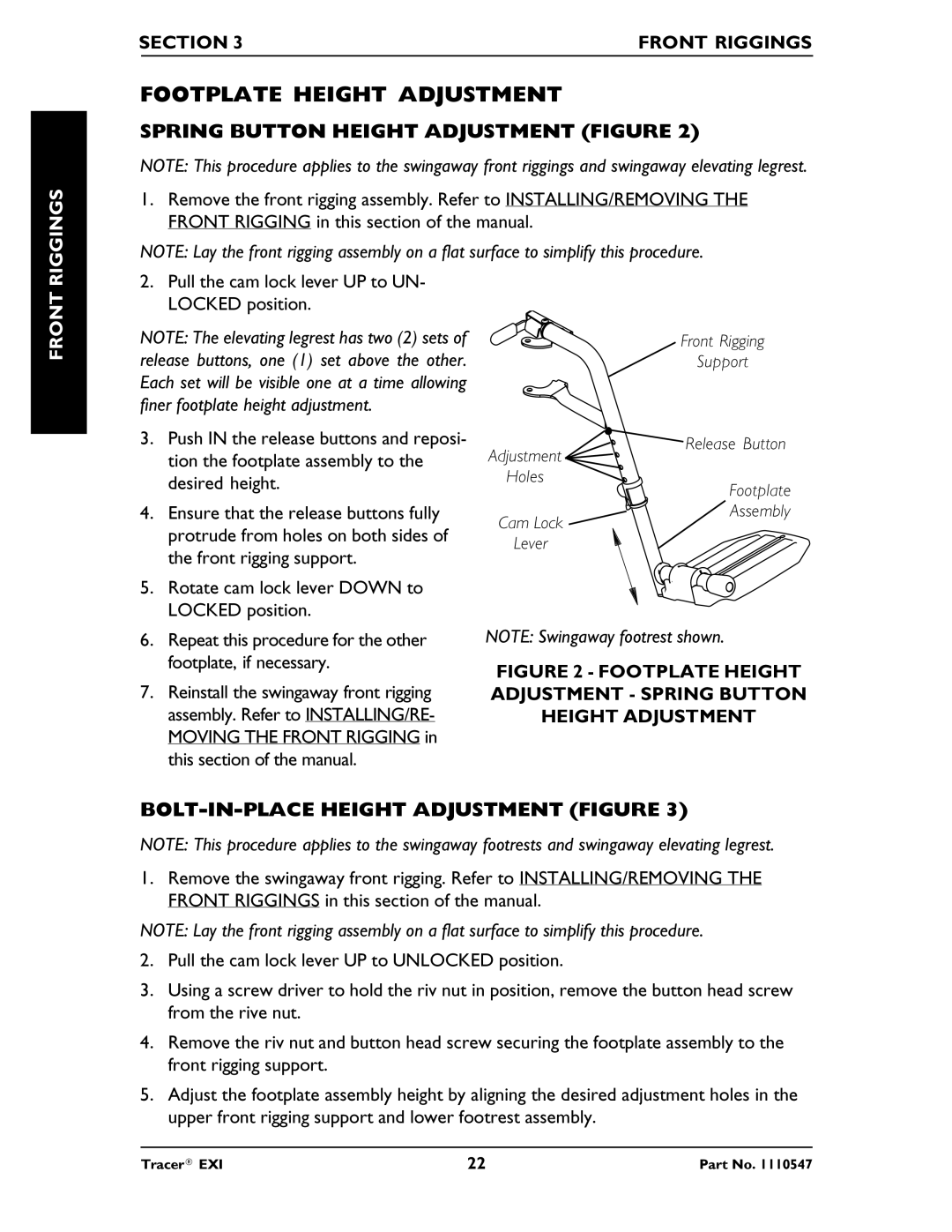
Front Rigging
release buttons, one (1) set above the other. Each set will be visible one at a time allowing finer footplate height adjustment.
3. Push IN the release buttons and reposi- |
tion the footplate assembly to the |
Adjustment
Support
Release Button
desired height. |
Holes
Footplate
4. | Ensure that the release buttons fully |
| protrude from holes on both sides of |
| the front rigging support. |
5. | Rotate cam lock lever DOWN to |
| LOCKED position. |
Cam Lock
Lever
Assembly
6. | Repeat this procedure for the other |
| footplate, if necessary. |
7. | Reinstall the swingaway front rigging |
| assembly. Refer to INSTALLING/RE- |
| MOVING THE FRONT RIGGING in |
| this section of the manual. |
NOTE: Swingaway footrest shown.
FIGURE 2 - FOOTPLATE HEIGHT ADJUSTMENT - SPRING BUTTON HEIGHT ADJUSTMENT
BOLT-IN-PLACE HEIGHT ADJUSTMENT (FIGURE 3)
NOTE: This procedure applies to the swingaway footrests and swingaway elevating legrest.
1.Remove the swingaway front rigging. Refer to INSTALLING/REMOVING THE FRONT RIGGINGS in this section of the manual.
NOTE: Lay the front rigging assembly on a flat surface to simplify this procedure.
2.Pull the cam lock lever UP to UNLOCKED position.
3.Using a screw driver to hold the riv nut in position, remove the button head screw from the rive nut.
4.Remove the riv nut and button head screw securing the footplate assembly to the front rigging support.
5.Adjust the footplate assembly height by aligning the desired adjustment holes in the upper front rigging support and lower footrest assembly.
Tracer® EXI | 22 | Part No. 1110547 |