CV-M4+/M4+CL, CV-M7+/M7+CL
7. Configuring the Camera
7.1. Mode setting SW1 on rear
SHUTTER
EXT.
TRIGGER
SCANNING
Rear SW
OFF | ON |
| 1 |
| 2 |
| 3 |
| 4 |
| 5 |
| 6 |
| 7 |
| 8 |
9
10
1/24 | 1/50 | 1/100 | 1/200 | 1/400 | 1/800 | 1/1500 | 1/3000 | 1/5000 | 1/10,000 | seconds |
< | < | < | < | < | < | < | < | > | > |
|
< | < | < | < | > | > | > | > | < | < |
|
< | < | > | > | < | < | > | > | < | < |
|
< | > | < | > | < | > | < | > | < | > | Frame delay |
< | > | < | > |
| Off | Edge presel. | Pulse width | |||
< | < | > | > |
|
|
| part.1/2 | part.1/4 | part.1/8 |
|
< | < | > | > |
| Full |
|
| |||
|
|
|
|
|
|
| ||||
< | > | < | > |
|
|
|
|
|
|
|
Normal < > |
|
| ||||||||
Local |
| < | > | RS232C |
|
|
| |||
Fig. 25. SW1 on camera rear
7.2. Mode setting SW301 inside
Switch shown with factory settings. SW 6 Binning, for M4+/M4+CL only.
Internal SW |
|
|
| - | Low active | Internal SW |
|
|
| |||
OFF | ON |
|
|
| + | High active |
| OFF | ON |
|
|
|
TRIGGER sel | 1 | LVDS | < | > Hirose |
| TRIGGER sel | 1 | LVDS | < | > Hirose | ||
TRIGGER pol | 2 | + | < | > | - |
| TRIGGER pol | 2 | + | < | > | - |
LEN/FEN/EEN pol | 3 | + | < | > | - | LEN/FEN/EEN pol | 3 | + | < | > | - | |
MULTIPLE EXP. | 4 | Off | < | > | On |
| MULTIPLE EXP. | 4 | Off |
| < | > On |
NC | 5 | Off | < | > | Ver |
| NC | 5 |
|
|
|
|
BINNING | 6 |
| BINNING | 6 | Off | < | > | Ver | ||||
NC | 7 |
|
|
|
|
| NC | 7 |
|
|
|
|
NC | 8 |
|
|
|
|
| NC | 8 |
|
|
|
|
M4+/M7+ | Shown in factory settings | M4+CL/M7+CL |
|
Fig. 26. Internal Switch
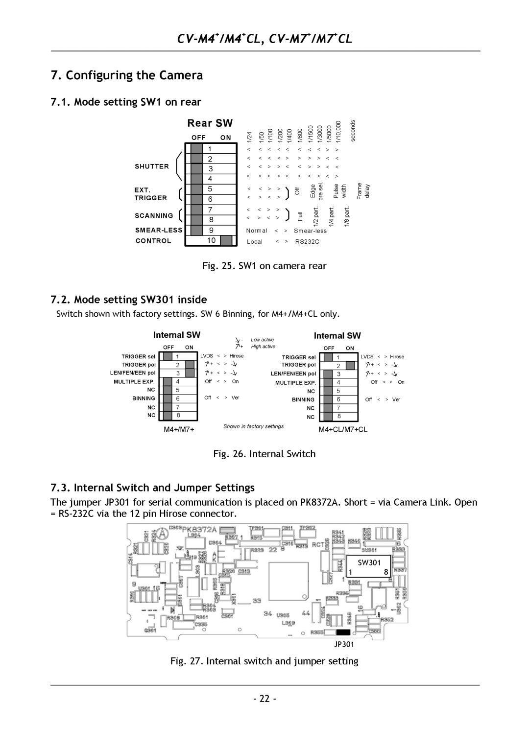
7.3. Internal Switch and Jumper Settings
The jumper JP301 for serial communication is placed on PK8372A. Short = via Camera Link. Open =
SW301
1 8
JP301
Fig. 27. Internal switch and jumper setting
- 22 -