Assembly
For assembly convenience, the item letter designators used throughout the Assembly section are the same as those used to identify shipping content and hardware components on pages
Stand Assembly
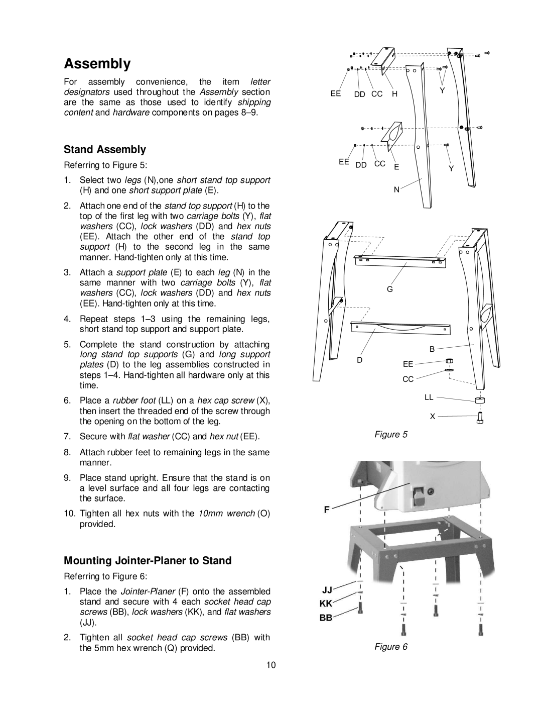
Referring to Figure 5:
1.Select two legs (N),one short stand top support
(H)and one short support plate (E).
2.Attach one end of the stand top support (H) to the top of the first leg with two carriage bolts (Y), flat washers (CC), lock washers (DD) and hex nuts
(EE). Attach the other end of the stand top support (H) to the second leg in the same manner.
3.Attach a support plate (E) to each leg (N) in the same manner with two carriage bolts (Y), flat washers (CC), lock washers (DD) and hex nuts
(EE).
4.Repeat steps
5.Complete the stand construction by attaching long stand top supports (G) and long support plates (D) to the leg assemblies constructed in steps
6.Place a rubber foot (LL) on a hex cap screw (X), then insert the threaded end of the screw through the opening on the bottom of the leg.
7.Secure with flat washer (CC) and hex nut (EE).
8.Attach rubber feet to remaining legs in the same manner.
9.Place stand upright. Ensure that the stand is on a level surface and all four legs are contacting the surface.
10.Tighten all hex nuts with the 10mm wrench (O) provided.
Mounting Jointer-Planer to Stand
Referring to Figure 6:
1.Place the
2.Tighten all socket head cap screws (BB) with the 5mm hex wrench (Q) provided.
10
EE | DD CC | H | Y |
|
EE DD CC E | Y |
N |
|
G
B ![]()
D EE
CC
LL
X
Figure 5
Figure 6