Adjustments
Cutterhead Knife Adjustment
![]() Cutterhead knives are dangerously sharp! Use extreme caution when inspecting, removing, sharpening or replacing knives into the cutterhead. Failure to comply may cause serious injury!
Cutterhead knives are dangerously sharp! Use extreme caution when inspecting, removing, sharpening or replacing knives into the cutterhead. Failure to comply may cause serious injury!
Determining if adjustment is necessary:
1.Disconnect machine from the power source.
2.Remove the cutterhead guard.
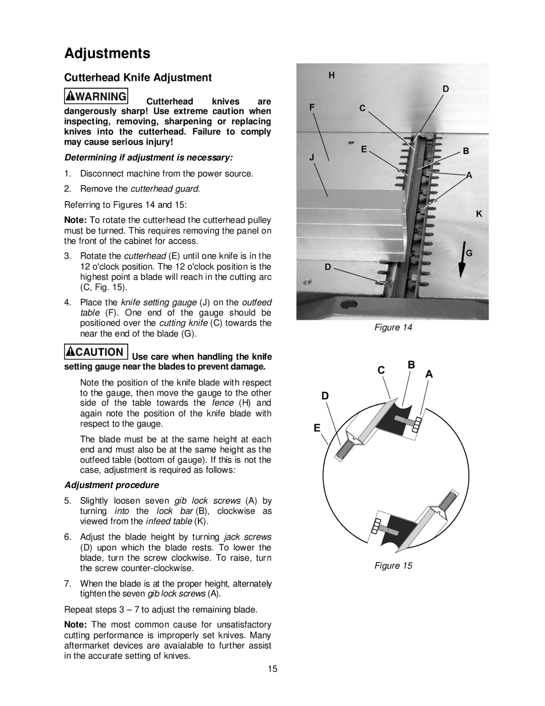
Referring to Figures 14 and 15:
Note: To rotate the cutterhead the cutterhead pulley must be turned. This requires removing the panel on the front of the cabinet for access.
3.Rotate the cutterhead (E) until one knife is in the 12 o'clock position. The 12 o'clock position is the highest point a blade will reach in the cutting arc (C, Fig. 15).
4.Place the knife setting gauge (J) on the outfeed table (F). One end of the gauge should be positioned over the cutting knife (C) towards the near the end of the blade (G).
![]() Use care when handling the knife setting gauge near the blades to prevent damage.
Use care when handling the knife setting gauge near the blades to prevent damage.
Note the position of the knife blade with respect to the gauge, then move the gauge to the other side of the table towards the fence (H) and again note the position of the knife blade with respect to the gauge.
The blade must be at the same height at each end and must also be at the same height as the outfeed table (bottom of gauge). If this is not the case, adjustment is required as follows:
Adjustment procedure
5.Slightly loosen seven gib lock screws (A) by turning into the lock bar (B), clockwise as viewed from the infeed table (K).
6.Adjust the blade height by turning jack screws
(D)upon which the blade rests. To lower the blade, turn the screw clockwise. To raise, turn the screw
7.When the blade is at the proper height, alternately tighten the seven gib lock screws (A).
Repeat steps 3 – 7 to adjust the remaining blade.
Note: The most common cause for unsatisfactory cutting performance is improperly set knives. Many aftermarket devices are avaialable to further assist in the accurate setting of knives.
Figure 14
B
C A
D
E
Figure 15
15