Operating Controls
![]() Disconnect machine from power source before making any adjustments. Failure to comply may cause serious injury.
Disconnect machine from power source before making any adjustments. Failure to comply may cause serious injury.
Power
Plug power cord into outlet.
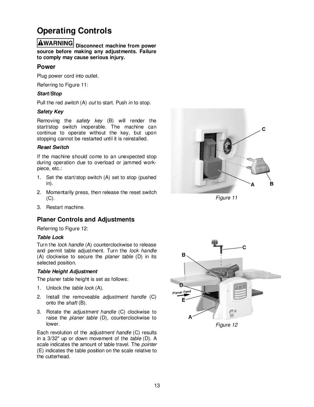
Referring to Figure 11:
Start/Stop
Pull the red switch (A) out to start. Push in to stop.
Safety Key
Removing the safety key (B) will render the start/stop switch inoperable. The machine can continue to operate without the key, but upon stopping cannot be restarted until it is reinstalled.
Reset Switch
If the machine should come to an unexpected stop during operation due to overload or jammed work- piece, etc.:
1.Set the start/stop switch (A) set to stop (pushed in).
2.Momentarily press, then release the reset switch
(C).
3.Restart machine.
Planer Controls and Adjustments
Referring to Figure 12:
Table Lock
Turn the lock handle (A) counterclockwise to release and permit table adjustment. Turn the lock handle
(A)clockwise to secure the planer table (D) in its selected position.
Table Height Adjustment
The planer table height is set as follows:
1.Unlock the table lock (A).
2.Install the removeable adjustment handle (C) onto the shaft (B).
3.Rotate the adjustment handle (C) clockwise to raise the planer table (D), counterclockwise to lower.
Each revolution of the adjustment handle (C) results in a 3/32" up or down movement of the table (D). A scale indicates the amount of table travel. The pointer
(E)indicates the table position on the scale relative to the cutterhead.
Figure 11
Figure 12
13