table, until it is level with the saw table (Figure 17). As one part of the edge becomes level with the table, tighten the clamp on that side. Then move to the other side and repeat, until the full length of the edge is level with the saw table. Lay a straight edge across both extension table and saw table to ensure proper leveling.
When the extension table is properly aligned, holes need to be drilled into the wood table using the holes in the rails as your guide (Figure 18). You may wish to drill 3/32" pilot holes first.
3.Drill 1/4" holes into the front edge of the table using the holes in the front rail as a guide. Drill 1/4" holes into the back edge of the table using the holes in the back rail as a guide.
If you have a 30” Rail System go to Step 4. For a 52” Rail System, go to Step 5.
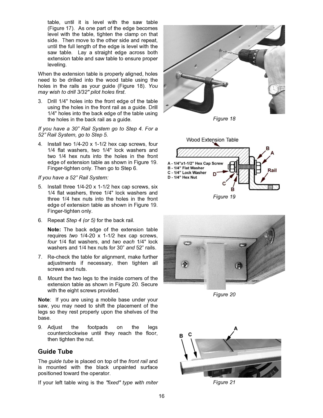
4.Install two
If you have a 52” Rail System:
5.Install three
6.Repeat Step 4 (or 5) for the back rail.
Note: The back edge of the extension table requires two
7.
8.Mount the two legs to the inside corners of the extension table as shown in Figure 20. Secure with the eight screws provided.
Note: If you are using a mobile base under your saw, you may need to shift the placement of the legs so they rest properly upon the shelves of the base.
9. Adjust the footpads on the legs counterclockwise until they reach the floor, then tighten the nut.
Guide Tube
The guide tube is placed on top of the front rail and is mounted with the black unpainted surface positioned toward the operator.
If your left table wing is the "fixed" type with miter
Figure 18
Figure 19
Figure 20
Figure 21
16