Blade Guard Assembly
Hardware: Blade Guard Assembly, Splitter Guard Assembly
Tools: 12mm Wrench, 17mm Wrench or Adjustable Wrench, 3mm Hex Wrench
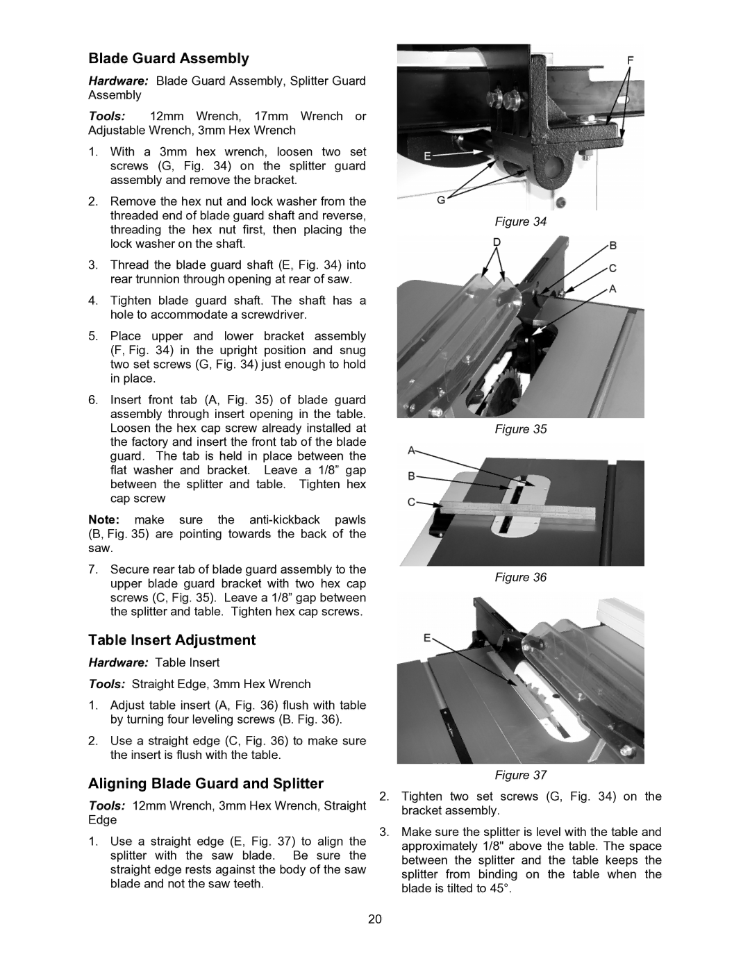
1.With a 3mm hex wrench, loosen two set screws (G, Fig. 34) on the splitter guard assembly and remove the bracket.
2.Remove the hex nut and lock washer from the threaded end of blade guard shaft and reverse, threading the hex nut first, then placing the lock washer on the shaft.
3.Thread the blade guard shaft (E, Fig. 34) into rear trunnion through opening at rear of saw.
4.Tighten blade guard shaft. The shaft has a hole to accommodate a screwdriver.
5.Place upper and lower bracket assembly (F, Fig. 34) in the upright position and snug two set screws (G, Fig. 34) just enough to hold in place.
6.Insert front tab (A, Fig. 35) of blade guard assembly through insert opening in the table. Loosen the hex cap screw already installed at the factory and insert the front tab of the blade guard. The tab is held in place between the flat washer and bracket. Leave a 1/8” gap between the splitter and table. Tighten hex cap screw
Note: make sure the
7.Secure rear tab of blade guard assembly to the upper blade guard bracket with two hex cap screws (C, Fig. 35). Leave a 1/8” gap between the splitter and table. Tighten hex cap screws.
Table Insert Adjustment
Hardware: Table Insert
Tools: Straight Edge, 3mm Hex Wrench
1.Adjust table insert (A, Fig. 36) flush with table by turning four leveling screws (B. Fig. 36).
2.Use a straight edge (C, Fig. 36) to make sure the insert is flush with the table.
Aligning Blade Guard and Splitter
Tools: 12mm Wrench, 3mm Hex Wrench, Straight Edge
1.Use a straight edge (E, Fig. 37) to align the splitter with the saw blade. Be sure the straight edge rests against the body of the saw blade and not the saw teeth.
Figure 34
Figure 35
Figure 36
Figure 37
2.Tighten two set screws (G, Fig. 34) on the bracket assembly.
3.Make sure the splitter is level with the table and approximately 1/8" above the table. The space between the splitter and the table keeps the splitter from binding on the table when the blade is tilted to 45°.
20