368262-UIM-B-1008
THERMOSTAT | THERMOSTAT | THERMOSTAT | |
|
|
| |
| *BP21H50124 |
| |
*DN22U00124 | *BN21H00124 | *DP32H70124 | |
*DP21H40124 | |||
|
| ||
| *DN21H00124 |
| |
|
|
|
| ID MODELS |
|
| OD MODELS |
| |||
TP(8,L)C |
|
| YZB |
|
| |||
YP(8,L)C |
|
| YMB |
|
| |||
CP(8,L)C |
|
|
| H*3 |
|
| ||
LP(8,L)C |
|
|
|
|
|
| ||
|
|
|
|
|
|
|
|
|
| MODULATING |
|
|
| SINGLE STAGE |
| ||
| FURNACE |
|
|
| HEAT PUMP |
| ||
|
|
|
|
|
|
|
|
|
|
|
|
|
|
|
|
| C | C | C |
|
|
|
| 24 – Volt Common | 24 – Volt Common | 24 – Volt Common |
|
|
|
|
|
|
|
|
|
|
| Y1 | Y1 | Y1 |
|
|
|
| First Stage Compressor | First Stage Compressor | First Stage Compressor |
|
|
|
|
|
|
|
|
|
|
| R | R | R |
|
|
|
| 24 – Volt Hot |
|
|
| ||
| (Heat XFMR) | 24 – Volt Hot | 24 – Volt Hot |
|
|
|
|
|
|
|
|
| |
| G | G | G |
|
|
|
| Fan | Fan | Fan |
|
|
|
|
|
|
|
|
|
|
| E | E | E |
|
|
|
| Emergency Heat | Emergency Heat | Emergency Heat |
|
|
|
|
|
|
|
|
|
|
|
|
| W2 |
|
|
|
|
|
| Third Stage Heat |
|
|
|
|
|
|
|
|
|
|
| R |
|
|
|
|
|
| 24 – Volt Hot |
|
|
|
|
|
|
|
|
|
|
| |
| (Cool XFMR) |
|
|
|
|
|
| O/B | O | O |
|
|
|
| Reversing Valve | Reversing Valve |
|
|
| |
| Reversing Valve |
|
|
| ||
| Energized in Cool | Energized in Cool |
|
|
| |
|
|
|
|
| ||
| L | L | L |
|
|
|
| Malfunction Light | Malfunction Light | Malfunction Light |
|
|
|
|
|
|
|
|
|
|
| Y2 | Y2 | Y2 |
|
|
|
| Second | Second | Second |
|
|
|
| Stage Compressor | Stage Compressor | Stage Compressor |
|
|
|
| AUX | W2 | W1 |
|
|
|
| Auxiliary Heat | Second Stage Heat | Second Stage Aux. Heat |
|
|
|
|
|
|
|
|
|
|
|
|
|
|
|
|
|
|
|
|
|
|
|
|
|
| 3 | External Humidistat |
|
|
|
|
| (Optional) |
|
|
| |
|
|
|
|
|
| |
|
|
| Open on Humidity Rise |
|
|
|
|
|
|
|
|
| |
|
|
|
|
|
|
|
| Thermostat Installer Setup | B/O Switch on Thermostat | Step 1 of Thermostat |
|
|
|
| Installer / Configuration |
|
|
| ||
| to 5 – 2 Heat/1 Heat Pump | must be in the O position | Menu must be set to |
|
|
|
| Thermostat Installer Setup |
| Heat Pump 1 |
|
|
|
|
|
|
|
|
| |
| be set to 0 – O/B terminal |
|
|
|
|
|
| Energized in Cooling |
|
|
|
|
|
|
|
|
|
|
|
|
MODULATING
FURNACE CONTROL
C
24 – Volt Common
Y1
Single
Stage Compressor
R
24 – Volt Hot
G
Fan
W
Modulating Heat
Y/Y2
Second or Full
Stage Compressor
O
Reversing Valve
Energized in Cool
LO COMP
Single Stage
Compressor (OUT)
HI COMP
Second Stage
Compressor (OUT)
DHUM
Dehumidification-
Open on Humidity Rise
Move HUMIDISTAT
jumper to “YES”
if humidistat is to be used.
2
Bonnet Sensor
(Optional)
YORKGUARD VI
CONTROL
C
24 – Volt Common
Y1
Single
Stage Compressor
R
24 – Volt Hot
W1 OUT
First Stage Heat
W2 OUT
Second Stage Heat
Y2 OUT
Second
Stage Compressor
O
Reversing Valve
Energized in Cool
X/L
Malfunction Light
Y2
Second
Stage Compressor
W
Auxiliary Heat
BSG
Bonnet Sensor
BS
Bonnet Sensor
Change FFuel jumper
on the heat pump control
to “ON”
Change Hot Heat Pump
jumper on the heat
pump control to “ON” if
Hot Heat Pump
Operation is desired.
1
3 | Part Number: |
| |
|
|
Part Numbers: | 2 | Part Numbers: | 1 | ||
SAP | = Legacy | ||||
SAP = Legacy |
|
| |||
| 126768 = |
| |||
|
|
| |||
|
| 18395 | = |
| |
|
| 340512 = |
| ||
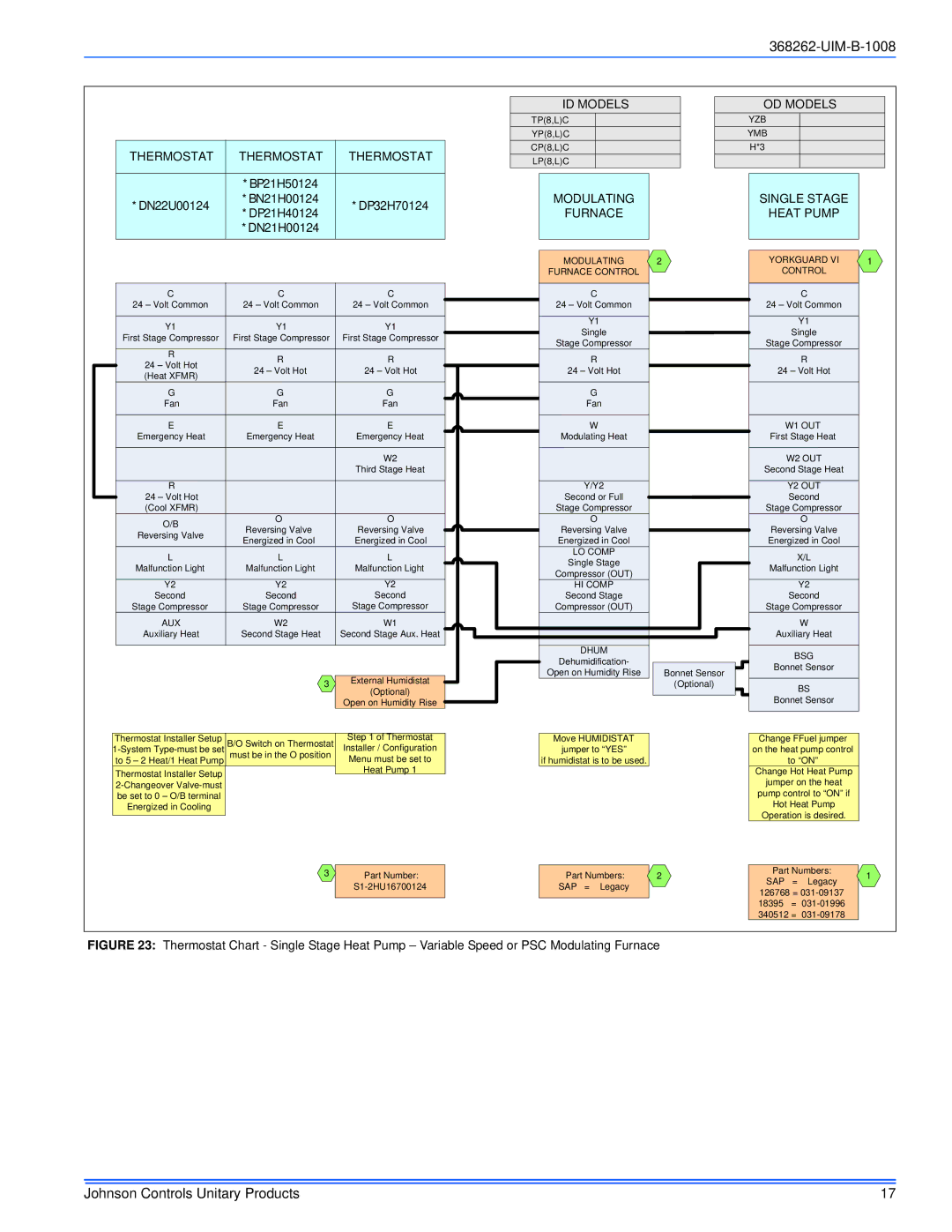
FIGURE 23: Thermostat Chart - Single Stage Heat Pump – Variable Speed or PSC Modulating Furnace
Johnson Controls Unitary Products | 17 |