Table 6: Ratings & Physical / Electrical Data
| Input |
| Output | Nominal | Air Temp. Rise | Air Temp. Rise | ||||||
Max/Min |
| Max/Min | Airflow | Max Input | Min Input | |||||||
MBH |
| kW | MBH |
| kW | CFM | m3/min | °F | °C | °F |
| °C |
60/30 |
| 17.6/8.8 | 47/24 |
| 13.8/7.0 | 1200 | 34.0 |
| ||||
80/40 |
| 23.5/11.8 | 62/32 |
| 18.2/9.4 | 1200 | 34.0 |
| ||||
80/40 |
| 23.5/11.8 | 62/32 |
| 18.2/9.4 | 1600 | 45.3 |
| ||||
100/50 |
| 29.3/14.7 | 78/40 |
| 22.8/11.7 | 1600 | 45.3 |
| ||||
100/50 |
| 29.3/14.7 | 78/40 |
| 22.8/11.7 | 2000 | 56.6 |
| ||||
120/60 |
| 33.7/16.9 | 95/48 |
| 27.8/14.1 | 2000 | 56.6 |
| ||||
Max. | Outlet |
| Blower | Blower | AFUE | Max | Total Unit | Min. wire Size | ||||
Air Temp |
| Wheel | (awg) @ 75 ft | |||||||||
|
|
| % | Amps | ||||||||
°F |
| °C | HP |
| Amps | size | Protect | one way | ||||
|
|
|
| |||||||||
160 |
| 71.1 | 1/2 |
| 4.8 | 11 x 8 | 80.0 | 15 | 7.0 |
| 14 | |
170 |
| 76.7 | 1/2 |
| 4.8 | 11 x 8 | 80.0 | 15 | 7.5 |
| 14 | |
165 |
| 73.9 | 3/4 |
| 7.5 | 11 x 10 | 80.0 | 15 | 10.0 |
| 14 | |
165 |
| 73.9 | 3/4 |
| 7.5 | 11 x 10 | 80.0 | 15 | 10.0 |
| 14 | |
165 |
| 73.9 | 1 |
| 14.5 | 11 x 11 | 80.0 | 20 | 12.0 |
| 12 | |
175 |
| 79.4 | 1 |
| 14.5 | 11 x 11 | 80.0 | 20 | 12.0 |
| 12 | |
Annual Fuel Utilization Efficiency (AFUE) numbers are determined in accordance with DOE Test procedures.
Wire size and over current protection must comply with the National Electrical Code
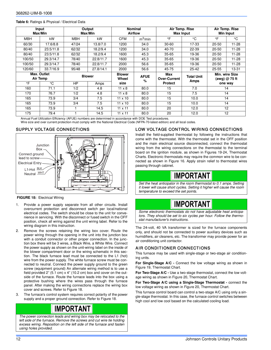
SUPPLY VOLTAGE CONNECTIONS
Junction Box
Connect ground lead to screw
Electrical Entry ![]()
Neutral WHT
FIGURE 18: Electrical Wiring
1.Provide a power supply separate from all other circuits. Install overcurrent protection and disconnect switch per local/national electrical codes. The switch should be close to the unit for conve- nience in servicing. With the disconnect or fused switch in the OFF position, check all wiring against the unit wiring label. Refer to the wiring diagram in this instruction.
2.Remove the screws retaining the wiring box cover. Route the power wiring through the opening in the unit into the junction box with a conduit connector or other proper connection. In the junc- tion box there will be 3 wires, a Black Wire, a White Wire. Connect the power supply as shown on the
3.The furnace's control system requires correct polarity of the power supply and a proper ground connection. Refer to Figure 18.
The power connection leads and wiring box may be relocated to the left side of the furnace. Remove the screws and cut wire tie holding excess wiring. Reposition on the left side of the furnace and fasten using holes provided.
LOW VOLTAGE CONTROL WIRING CONNECTIONS
Install the
Set the heat anticipator in the room thermostat to 0.1 amps. Setting it lower will cause short cycles. Setting it higher will cause the room temperature to exceed the set points.
Some electronic thermostats do not have adjustable heat anticipa- tors. They should be set to six cycles per hour. Follow the thermo- stat manufacturer's instructions.
The
AIR CONDITIONER CONNECTIONS
This furnace may be used with
For
For
For
This furnace control board can control a
12 | Johnson Controls Unitary Products |