The Front Panel
THE FRONT PANEL
The features shared in common by
•A System Status LED display
•An Asset Recovery Pinhole
•A Console port
•A Modem port
•A Compact Flash Card Slot
•Ethernet interfaces
System Status LED Display
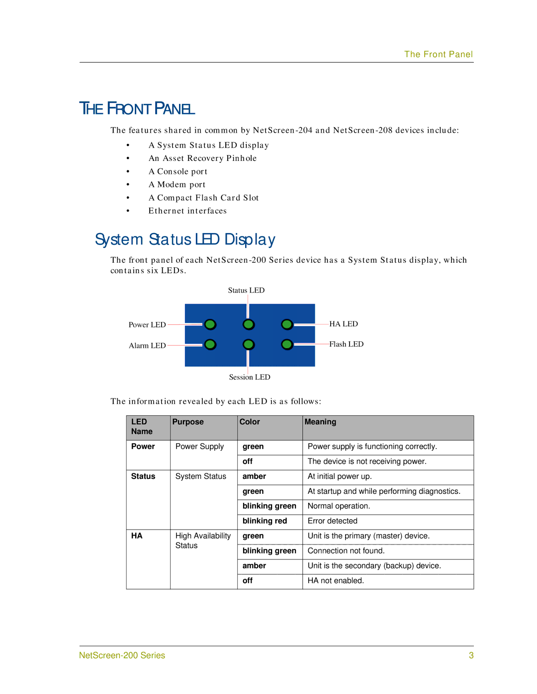
The front panel of each
|
| Status LED | |||||
Power LED |
|
|
|
|
| HA LED | |
|
|
|
|
| |||
|
|
|
|
| |||
Alarm LED |
|
|
|
|
|
| Flash LED |
|
|
|
|
|
| ||
|
|
|
|
|
| ||
Session LED
The information revealed by each LED is as follows:
LED | Purpose | Color | Meaning |
Name |
|
|
|
|
|
|
|
Power | Power Supply | green | Power supply is functioning correctly. |
|
|
|
|
|
| off | The device is not receiving power. |
|
|
|
|
Status | System Status | amber | At initial power up. |
|
|
|
|
|
| green | At startup and while performing diagnostics. |
|
|
|
|
|
| blinking green | Normal operation. |
|
|
|
|
|
| blinking red | Error detected |
|
|
|
|
HA | High Availability | green | Unit is the primary (master) device. |
| Status |
|
|
| blinking green | Connection not found. | |
|
| ||
|
|
|
|
|
| amber | Unit is the secondary (backup) device. |
|
|
|
|
|
| off | HA not enabled. |
|
|
|
|
3 |
