Component Names & Functions
Rear Panel
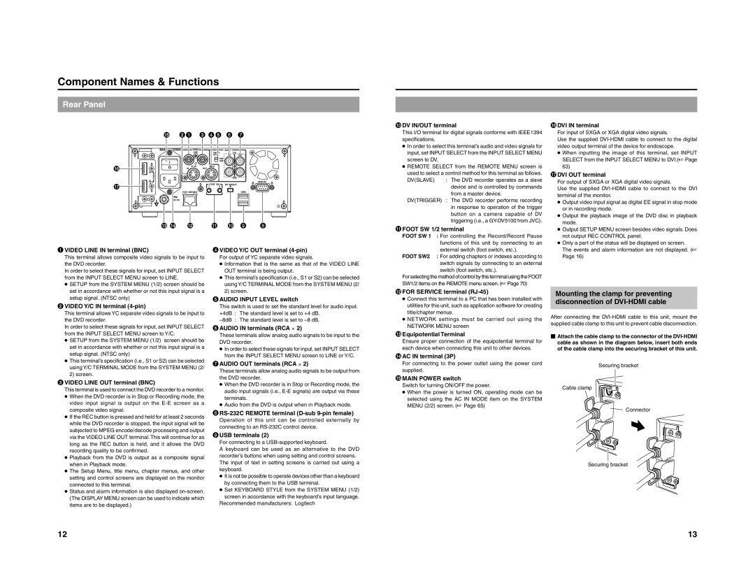
| % | 21 | 3 45 6 7 | |
| MAIN | POWER | VIDEO | | | AUDIO | | |
| | | LINE | | INPUT | CH1 | | |
| | | | | LEVEL | IN | OUT | |
| | | | | +4dB | | | |
| | | | | -8dB | | | |
^ | | | Y/C | OUT | Y/C | | | |
| | IN | | | | |
| IN | | | | | | | |
| DVI | | | | | CH2 | | |
& | OUT | | | FOOT SW | DV IN/OUT | | REMOTE |
| | | | |
| | | 1 | 2 | | | |
| | | FOR SERVICE | | | | USB | |
| | AC IN | | | | | | |
| # $ | @ | | ! | 0 | 9 | 8 |
0DV IN/OUT terminal
This I/O terminal for digital signals conforms with IEEE1394 specifications.
●In order to select this terminal’s audio and video signals for input, set INPUT SELECT from the INPUT SELECT MENU screen to DV.
●REMOTE SELECT from the REMOTE MENU screen is
used to select a control method for this terminal as follows.
DV(SLAVE) : The DVD recorder operates as a slave device and is controlled by commands from a master device.
DV(TRIGGER) : The DVD recorder performs recording in response to operation of the trigger button on a camera capable of DV triggering (i.e., a GY-DV5100 from JVC).
!FOOT SW 1/2 terminal
FOOT SW 1 : For controlling the Record/Record Pause functions of this unit by connecting to an
^DVI IN terminal
For input of SXGA or XGA digital video signals.
Use the supplied DVI-HDMI cable to connect to the digital video output terminal of the device for endoscope.
●When inputting the image of this terminal, set INPUT SELECT from the INPUT SELECT MENU to DVI.(☞ Page 63)
&DVI OUT terminal |
For output of SXGA or XGA digital video signals. |
Use the supplied DVI-HDMI cable to connect to the DVI |
terminal of the monitor. |
● Output video input signal as digital EE signal in stop mode |
or in recording mode. |
● Output the playback image of the DVD disc in playback |
mode. |
● Output SETUP MENU screen besides video signals. Does |
not output REC CONTROL panel. |
● Only a part of the status will be displayed on screen. |
1VIDEO LINE IN terminal (BNC)
This terminal allows composite video signals to be input to the DVD recorder.
In order to select these signals for input, set INPUT SELECT from the INPUT SELECT MENU screen to LINE.
●SETUP from the SYSTEM MENU (1/2) screen should be set in accordance with whether or not this input signal is a setup signal. (NTSC only)
2VIDEO Y/C IN terminal (4-pin)
This terminal allows YC separate video signals to be input to the DVD recorder.
In order to select these signals for input, set INPUT SELECT from the INPUT SELECT MENU screen to Y/C.
●SETUP from the SYSTEM MENU (1/2) screen should be set in accordance with whether or not this input signal is a setup signal. (NTSC only)
●This terminal’s specification (i.e., S1 or S2) can be selected using Y/C TERMINAL MODE from the SYSTEM MENU (2/ 2) screen.
3VIDEO LINE OUT terminal (BNC)
This terminal is used to connect the DVD recorder to a monitor.
●When the DVD recorder is in Stop or Recording mode, the video input signal is output on the E-E screen as a composite video signal.
●If the REC button is pressed and held for at least 2 seconds while the DVD recorder is stopped, the input signal will be subjected to MPEG encode/decode processing and output via the VIDEO LINE OUT terminal. This will continue for as long as the REC button is held, and it allows the DVD recording quality to be confirmed.
●Playback from the DVD is output as a composite signal when in Playback mode.
●The Setup Menu, title menu, chapter menus, and other setting and control screens are displayed on the monitor connected to this terminal.
●Status and alarm information is also displayed on-screen. (The DISPLAY MENU screen can be used to indicate which items are to be displayed.)
4VIDEO Y/C OUT terminal (4-pin)
For output of YC separate video signals.
●Information that is the same as that of the VIDEO LINE OUT terminal is being output.
●This terminal’s specification (i.e., S1 or S2) can be selected using Y/C TERMINAL MODE from the SYSTEM MENU (2/ 2) screen.
5AUDIO INPUT LEVEL switch
This switch is used to set the standard level for audio input. +4dB : The standard level is set to +4 dB.
–8dB : The standard level is set to –8 dB.
6AUDIO IN terminals (RCA ⋅ 2)
These terminals allow analog audio signals to be input to the DVD recorder.
●In order to select these signals for input, set INPUT SELECT from the INPUT SELECT MENU screen to LINE or Y/C.
7AUDIO OUT terminals (RCA ⋅ 2)
These terminals allow analog audio signals to be output from the DVD recorder.
●When the DVD recorder is in Stop or Recording mode, the audio input signals (i.e., E-E signals) are output via these terminals.
●Audio from the DVD is output when in Playback mode.
8RS-232C REMOTE terminal (D-sub 9-pin female)
Operation of this unit can be controlled externally by connecting to an RS-232C control device.
9USB terminals (2)
For connecting to a USB-supported keyboard.
A keyboard can be used as an alternative to the DVD recorder’s buttons when using setting and control screens. The input of text in setting screens is carried out using a keyboard.
●It is not be possible to operate devices other than a keyboard by connecting them to the USB terminal.
●Set KEYBOARD STYLE from the SYSTEM MENU (1/2) screen in accordance with the keyboard’s input language.
Recommended manufacturers: Logitech
external switch (foot switch, etc.).
FOOT SW2 : For adding chapters or indexes according to switch signals by connecting to an external switch (foot switch, etc.).
For selecting the method of control by this terminal using the FOOT SW1/2 items on the REMOTE menu screen. (☞ Page 70)
@FOR SERVICE terminal (RJ-45)
●Connect this terminal to a PC that has been installed with utilities for this unit, such as application software for creating title/chapter menus.
●NETWORK settings must be carried out using the NETWORK MENU screen
#Equipotential Terminal
Ensure proper connection of the equipotential terminal for each device when connecting this unit to other devices.
$AC IN terminal (3P)
For connecting to the power outlet using the power cord supplied.
%MAIN POWER switch
Switch for turning ON/OFF the power.
●When the power is turned ON, operating mode can be selected using the AC IN MODE item on the SYSTEM MENU (2/2) screen. (☞ Page 65)
The events and alarm information are not displayed. (☞ |
Page 16) |
Mounting the clamp for preventing
disconnection of DVI-HDMI cable
After connecting the DVI-HDMI cable to this unit, mount the supplied cable clamp to this unit to prevent cable disconnection.
�Attach the cable clamp to the connector of the DVI-HDMI cable as shown in the diagram below, insert both ends of the cable clamp into the securing bracket of this unit.
Securing bracket
Cable clamp
Connector
Securing bracket