Connections
Front & Rear Panel Diagrams
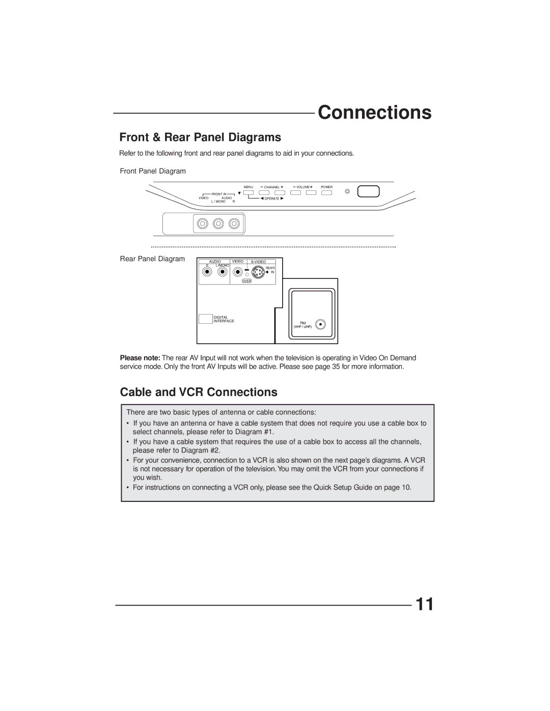
Refer to the following front and rear panel diagrams to aid in your connections.
Front Panel Diagram
MENU | CHANNEL | VOLUME | POWER |
FRONT IN |
| |
VIDEO | AUDIO | OPERATE |
L | MONO | R |
Rear Panel Diagram
| AUDIO | VIDEO | |
R | L MONO |
| REAR |
|
|
| |
|
|
| IN |
|
| OVER |
|
| DIGITAL |
|
|
| INTERFACE |
| |
Please note: The rear AV Input will not work when the television is operating in Video On Demand service mode. Only the front AV Inputs will be active. Please see page 35 for more information.
Cable and VCR Connections
There are two basic types of antenna or cable connections:
•If you have an antenna or have a cable system that does not require you use a cable box to select channels, please refer to Diagram #1.
•If you have a cable system that requires the use of a cable box to access all the channels, please refer to Diagram #2.
•For your convenience, connection to a VCR is also shown on the next page’s diagrams. A VCR is not necessary for operation of the television. You may omit the VCR from your connections if you wish.
•For instructions on connecting a VCR only, please see the Quick Setup Guide on page 10.
11
