REAR VIEW
<Rear Panel>
INPUT A | INPUT B |
|
(RGB/COMPO.) | (VIDEO) | Y/C |
IN OUT IN OUT
G/Y
|
|
| REMOTE | IN/OUT |
| B/P | HD/ | INPUT C |
|
| (RGB) |
| ||
AC INPUT | C |
|
| |
| VD | AUDIO INPUT | ||
|
|
| ||
|
| EXT SYNC | (MONO) | |
14
AC INPUT
| 8 |
|
|
| 9 | 10 | |||
|
|
|
|
|
|
|
|
|
|
INPUT A |
| INPUT B |
| |
(RGB/COMPO.) |
| (VIDEO) | Y/C | |
IN | OUT | IN | OUT |
|
G/Y |
|
|
|
|
B/PB |
| HD/ |
| INPUT C |
|
| (RGB) | ||
| CS |
|
| |
R/PR |
| VD |
|
|
|
|
|
| |
|
|
| EXT SYNC |
|
11
REMOTE IN/OUT
AUDIO INPUT![]()
(MONO)
15
AC outlet
(120 V AC, 60 Hz)
12
13
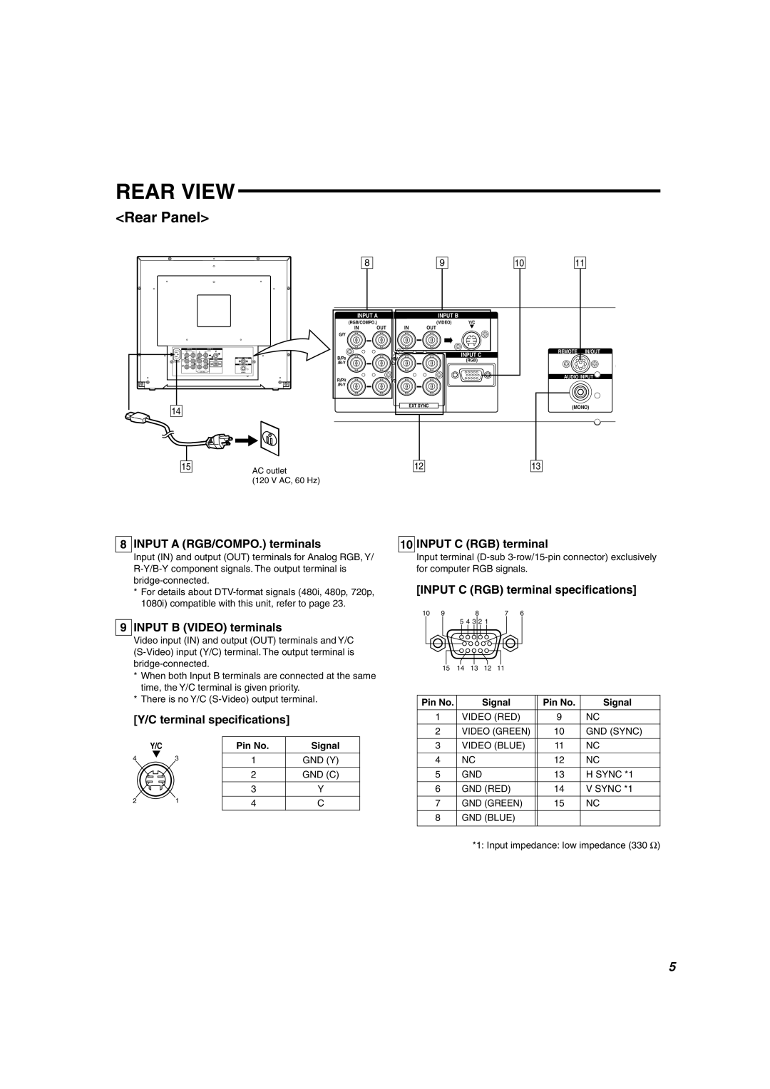
8 INPUT A (RGB/COMPO.) terminals
Input (IN) and output (OUT) terminals for Analog RGB, Y/
*For details about
9 INPUT B (VIDEO) terminals
Video input (IN) and output (OUT) terminals and Y/C
*When both Input B terminals are connected at the same time, the Y/C terminal is given priority.
*There is no Y/C
[Y/C terminal specifications]
| Y/C | Pin No. | Signal |
4 | 3 | 1 | GND (Y) |
|
| 2 | GND (C) |
|
| 3 | Y |
2 | 1 | 4 | C |
10 INPUT C (RGB) terminal
Input terminal
[INPUT C (RGB) terminal specifications]
10 | 9 |
| 8 |
| 7 | 6 |
|
|
|
| 5 4 3 2 1 |
|
|
|
| ||
| 15 | 14 | 13 | 12 | 11 |
|
|
|
Pin No. |
|
| Signal |
| Pin No. | Signal | ||
| 1 | VIDEO (RED) | 9 | NC | ||||
| 2 | VIDEO (GREEN) | 10 | GND (SYNC) | ||||
| 3 | VIDEO (BLUE) | 11 | NC | ||||
| 4 | NC |
|
|
| 12 | NC | |
| 5 | GND |
|
|
| 13 | H SYNC *1 | |
| 6 | GND (RED) |
| 14 | V SYNC *1 | |||
| 7 | GND (GREEN) | 15 | NC | ||||
| 8 | GND (BLUE) |
|
|
| |||
*1: Input impedance: low impedance (330 Ω)
5