Setup for Input Signals
Component/RGB-in Select
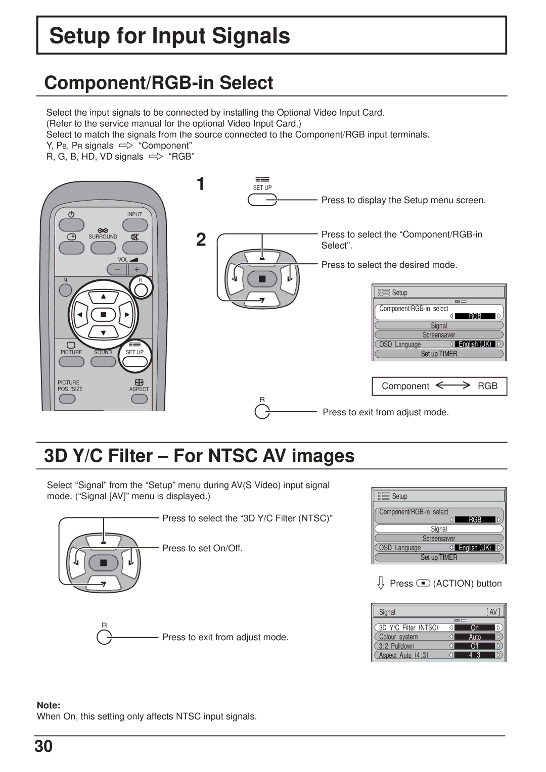
Select the input signals to be connected by installing the Optional Video Input Card. (Refer to the service manual for the optional Video Input Card.)
Select to match the signals from the source connected to the Component/RGB input terminals.
Y, PB, PR signals ![]() “Component”
“Component”
R, G, B, HD, VD signals ![]() “RGB”
“RGB”
|
| INPUT |
| SURROUND |
|
|
| VOL |
N |
| R |
PICTURE | SOUND | SET UP |
PICTURE |
|
|
POS. /SIZE |
| ASPECT |
1
2
SET UP
Press to display the Setup menu screen.
Press to select the
![]() Press to select the desired mode.
Press to select the desired mode.
Setup |
|
RGB | |
| |
Signal |
|
Screensaver | English (UK) |
OSD Language | |
Set up TIMER |
|
Component | RGB |
R
Press to exit from adjust mode.
3D Y/C Filter – For NTSC AV images
Select “Signal” from the “Setup” menu during AV(S Video) input signal mode. (“Signal [AV]” menu is displayed.)
Press to select the “3D Y/C Filter (NTSC)”
![]() Press to set On/Off.
Press to set On/Off.
R
![]() Press to exit from adjust mode.
Press to exit from adjust mode.
Setup |
|
RGB | |
| |
Signal |
|
Screensaver | English (UK) |
OSD Language | |
Set up TIMER |
|
Press ![]() (ACTION) button
(ACTION) button
Signal | [ AV ] |
3D Y/C Filter (NTSC) | On |
Colour system | Auto |
3:2 Pulldown | Off |
Aspect Auto (4:3) | 4 : 3 |
Note:
When On, this setting only affects NTSC input signals.
30