Connections
Component/RGB Input connection
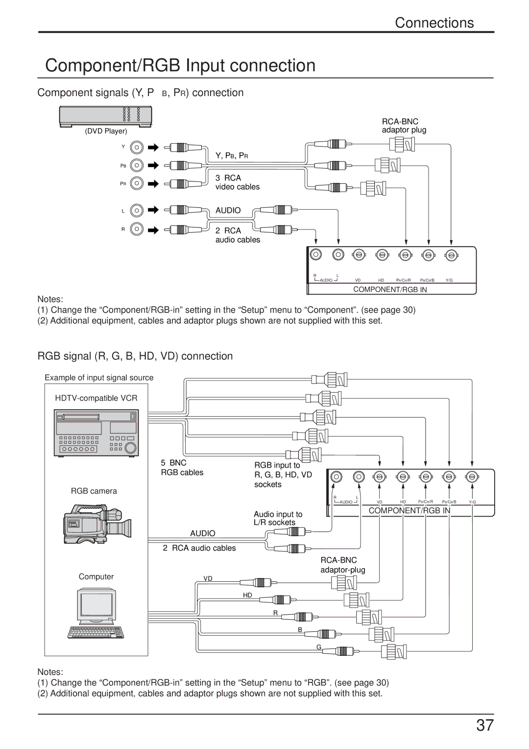
Component signals (Y, PB, PR) connection
| |
(DVD Player) | adaptor plug |
Y |
|
| Y, PB, PR |
PB
PR
L
R
3× RCA video cables
AUDIO
2× RCA ![]() audio cables
audio cables
R | L |
|
|
|
|
AUDIO | VD | HD | PR/CR/R | PB/CB/B | Y/G |
| COMPONENT/RGB IN |
| |||
Notes:
(1)Change the
(2)Additional equipment, cables and adaptor plugs shown are not supplied with this set.
RGB signal (R, G, B, HD, VD) connection
Example of input signal source
5× BNC |
| RGB input to |
|
|
RGB cables | R, G, B, HD, VD |
|
| |
|
|
|
| |
RGB camera |
| sockets |
|
|
| R | L |
| |
|
| HD PR/CR/R PB/CB/B | ||
|
| AUDIO | VD | |
|
| Audio input to | COMPONENT/RGB IN | |
|
|
|
| |
|
| L/R sockets |
|
|
| AUDIO |
|
|
|
2× RCA audio cables |
|
|
| |
|
|
| ||
Computer |
|
| ||
VD |
|
|
| |
HD
R
B
G![]()
Notes:
(1)Change the
(2)Additional equipment, cables and adaptor plugs shown are not supplied with this set.
Y/G
37