Model No Serial No GET0570-001A
For customer Use
Temperature inside the car
For safety
Information For U.S.A
Contents
FM/AM/HD RADIO/SIRIUS/XM Search for station/channel
Basic operations
Before using the remote controller
Using the remote controller RM-RK50
Display window
Enters the main menu with 5 U
Store the battery in a place where children cannot reach
Set the clock
Turn on the power
Cancel the display demonstrations
Preparation
Listening to the radio
When an FM stereo broadcast is hard to receive
Select FM or AM
Selecting a track/folder
Manual presetting FM/AM
Disc operations
Prohibiting disc ejection
Open
Registering a Bluetooth device Registration Pairing methods
Selecting the playback modes
Repeat Ô Random
Connecting a device
Registering using Open
When a text message comes
Using the Bluetooth cellular phone
Select BT-PHONE Enter the Bluetooth menu
When a call comes
Select BT-AUDIO
When receiving an HD Radio
What is HD Radio Technology?
Listening to the HD Radio Broadcast
Turn = Press
Enter the list mode
Listening to the CD changer
Select CD-CH
Check your Sirius ID, see
GCI Global Control Information update
Listening to the satellite radio
Activate your Sirius subscription after connection
Select a channel to listen
Selecting SIRIUS/XM preset station
Select Sirius or XM
Select a category
ONE RPT
Listening to the iPod
Select Ipod
Select a song
AUX auxiliary input jack on the control panel
Listening to the other external components
Selecting a preset sound mode
To erase the entire title
Title assignment
Auto Answer
Bluetooth settings
Version
Menu operations
SID*6
TAG on
Area
MONO*5
Loud Loud OFF
Mode SUB.W
FADER*9
BALANCE*10
Color settings
More about this unit
Ejecting a disc
Playing an MP3/WMA disc
Loading
Error
Reset
Unfound
Symptoms Remedies/Causes
Troubleshooting
Disc
Signal reception
Album name A limited number of symbols
Bluetooth device Device
Bluetooth cellular phone
HD Radio reception CD changer Symptoms Remedies/Causes
Bluetooth
Radio
IPod Symptoms
How to clean the connectors
Maintenance
Do not use the following discs
Power Output
Specifications
Audio Amplifier Section
General
CD Player Section
Call
Lista de piezas para instalación y conexión
Precautions on power supply and speaker connections
Parts list for installation and connection
Liste des pièces pour l’installation et raccordement
Extracción de la unidad Retrait de l’appareil
Installation Montage
Electrical Connections Conexiones Electricas
Precaucion
Precaution
CD Receiver
Do not raise the volume level too much, as this will
Contents
Confirm the selection Press.*3
FM/AM Select preset station CD/CD-CH Select folder
Time countdown indicator Disc
Changes the preset stations
If the current disc is an audio CD, no Name appears
Select Tuner = Mono
Select FM or AM Search for a station to listen-Auto Search
Turn on the power Insert a disc
MP3/WMA Select folder PressSelect track
Select BT-PHONE or BT-AUDIO Select NEW Device Select Open
Use the Bluetooth device to search and connect
Connect/disconnect/delete
Connecting/disconnecting/deleting a
Registered device
Selected device
Using the Bluetooth audio player
If there is no disc on the selected tray, the unit beeps
Playback starts automatically
Playback starts automatically
Select Ipod Select a song
Select EXT Input or AUX
Adjust the volume
Adjust the sound as you want see pages 17
Listening to the other external components
Select EQ = User
See also page 20 EQ
Show the title entry screen Assign a title
Bluetooth settings
SCROLL*2
Power is turned off
Repeat if necessary
Demo Demo on
Loud
Tuner
If Band
Fader
EXT IN*10 CH / Ipod
SUB.W
AMP GAIN*8
AM*9
Creating your own color -USER Color
Adjust the level 00 to 31 of the selected primary color
Select Color = User
Pickup lens inside the unit is dirty
Use only finalized CD-Rs or CD-RWs
MP3 files encoded in an inappropriate format
IPod
Disc playback
General Symptoms Remedies/Causes
MP3/WMA playback Symptoms Remedies/Causes
Bluetooth Symptoms Remedies/Causes
IPod Symptoms
Make sure to store discs in cases after use
New discs may have some rough spots
Distortion
Maximum Power Output
Per channel
Front/Rear
0C to +40C
Power Requirement Operating Voltage
Having Trouble with operation?
When installing the unit without using the sleeve
When using the optional stay
Removing the unit
Typical connections
Connecting the external amplifier or subwoofer
Connecting the external components
When connecting two components in series
KD-R406/KD-R405
Do not raise the volume level too much, as this will
Contents
Registered device
FM =AM*1 =CD*2 =CD-CH*2/IPOD*2or
On the next
Returns to the previous menu ∞ Confirms the selection
Preparation
Listening to the radio
Disc operations
Using the Bluetooth devices
Enter a PIN Personal Identification Number code to the unit
Entering a PIN code Confirm the entry
Making a call
Select BT-AUDIO
If there is no disc on the selected tray, the unit beeps
Listening to the iPod
Adjust the sound as you want see pages 17
Storing your own sound mode
Select FM or AM Show the title entry screen Assign a title
Bluetooth Audio Shows only Version
Menu items
BALANCE*6
Sound at a low volume level
MONO*3
FADER*5
EXT Input
Select a primary color
More about this unit
This unit cannot play back the following files
No available Bluetooth device is detected by Search
FM/AM
Playback
Bluetooth Symptoms Remedies/Causes
IPod Symptoms
New discs may have some rough spots
Holding it by the edges
Maximum Power Output Front/Rear Per channel
English References
EN, TH
KD-R406/KD-R405
√µ‘¥µ-Èß√ª√-Õ·ºßÀπȪí∑¡Ï‡¢È
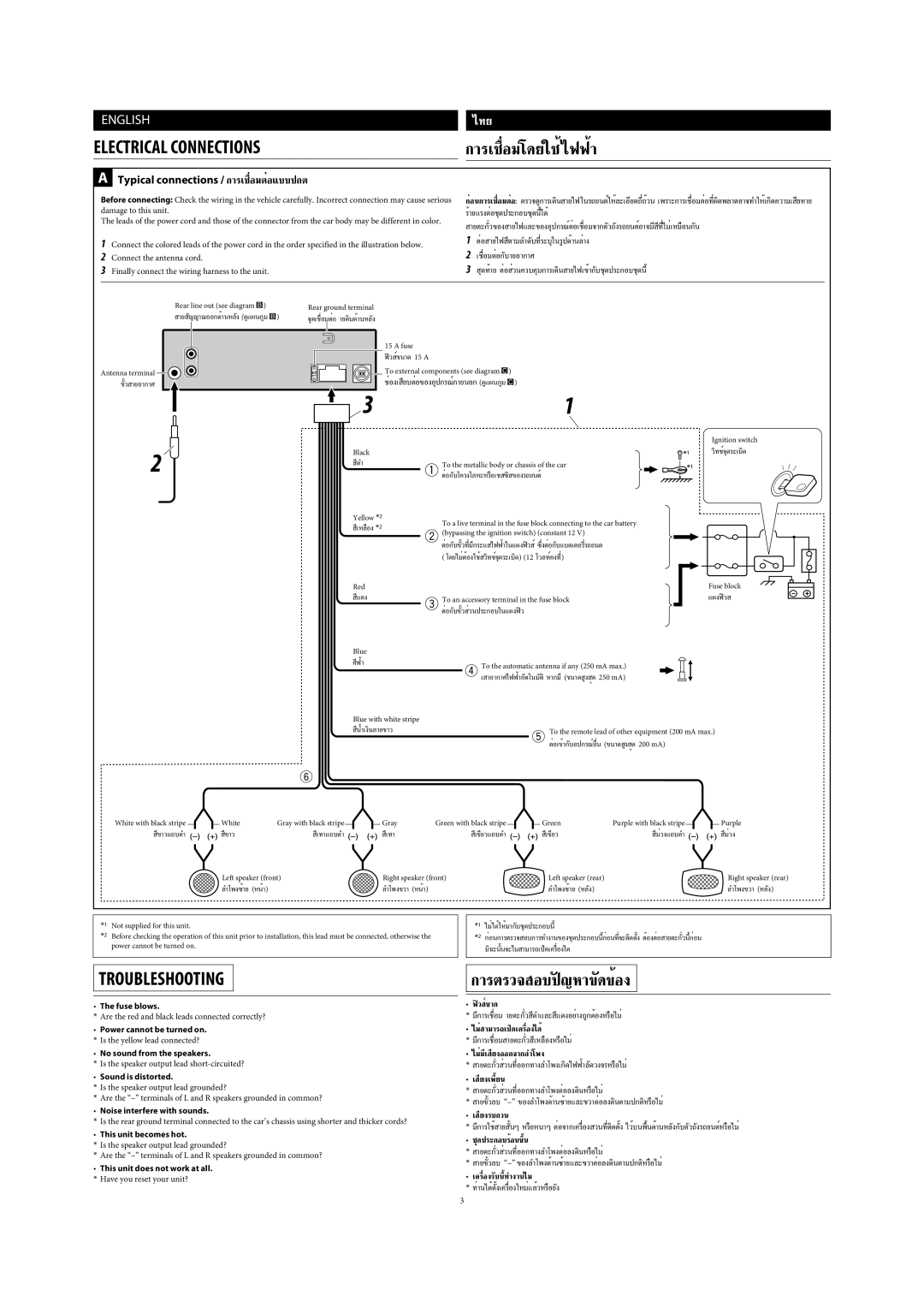
Typical connections / √‡ËÕ¡µËÕ·ªµ
√‡ËÕ¡‚¥¬„ȉøøÈ
‡¡ËÕ‡ËÕ¡µ Ë«πª√-Õ Õß‘Èπ·Õπÿ√¡
Daftar bagian-bagian untuk pemasangan dan penyambungan
Indonesia
Memindahkan unit
Pemasangan BINGKAI-DALAM Dash
Typical connections / Ciri khas sambungan-sambungan
SAMBUNGAN-SAMBUNGAN Listrik
Buku Petunjuk
Peringatan
GET0571-005A
Important for Laser Products
Contents
Basic operations
Using the remote controller RM-RK50
Returns to the previous menu ∞ Confirms the selection
Preparation
Listening to the radio
Disc operations
Using the Bluetooth devices
Digit number. Initial
Making a call
Select BT-AUDIO
Listening to the CD changer
Listening to the iPod
Listening to the other external components
Selecting a preset sound mode
Title assignment
Bluetooth settings
Dims the display and button illumination
When the unit receive a text message, the display only
Mode SUB.W
Color settings
More about this unit
Bluetooth operations
IPod
Troubleshooting
Playback
Bluetooth Symptoms Remedies/Causes
IPod Symptoms
Maintenance
Specifications
English References
EN, CT
安裝/連接手冊
安裝(裝設、固定在儀表板內)
When using the optional stay / 若選用支撐架
Typical connections / 典型的接線方法
Electrical Connections
When connecting two components in series / 當串聯兩件外接裝置時
Connecting the external components / 連接其他外接裝置
Model No Serial No GET0642-001A
For canceling the display demonstration, see
English
Attaching the control panel Detaching the control panel
Setting the clock
Canceling the display demonstration
Turn on the power
Using the control panel
Using the remote controller RM-RK50
Mode
Held
∞ to confirm the selection
Station name* = Frequency = Clock = back to the beginning
Change the display information
Change the display information Audio CD/CD Text
Stop playing and ejecting the disc
MP3/WMA
Using the Bluetooth devices
External Devices
Making a call
Select BT-AUDIO
See also Turn = Press
Changing HD Radio reception mode
Listening to the CD changer
Listening to the satellite radio
Storing channels in memory
Listening to the iPod
Listening to the other external components
Selecting a preset sound mode
Title assignment
Bluetooth settings
Display
Ring COLOR*8
FADER*9
Color settings
More about this unit
Bluetooth operations
Satellite radio IPod
Troubleshooting
English References
Avrcp Audio/Video Remote Control Profile
Radio
English
Maintenance
Subwoofer-Out Level/Impedance V/20 kΩ load full scale
≤ 1% THD+N
English References
EN, SP
DC, Negative ground / 12 V CC, Negativo a masa
This unit does not work at all. Have you reset your unit?
Component / Componente Adapter/System / Adaptador/Sistema
Important / Importante
Not recommended... / No recomendado
JVC component / Componente JVC

 )
)