6![]()
![]()
![]()
![]()
![]()
![]()
![]()
![]()
![]()
![]()
![]()
![]()
![]()
![]()
![]()
![]()
![]()
![]()
![]()
![]()
![]()
![]()
![]()
![]()
![]()
![]()
![]()
![]()
![]()
![]()
![]()
![]()
![]()
![]()
![]()
![]()
![]()
![]()
![]()
![]()
![]()
![]()
![]()
![]()
![]()
![]()
![]()
![]()
![]()
![]()
![]()
![]()
![]()
![]()
![]()
![]()
![]()
![]()
![]()
![]()
![]()
![]()
![]()
![]()
![]()
![]()
![]()
![]()
![]()
![]()
![]()
![]()
![]()
![]()
![]()
![]()
![]()
![]() I
I![]()
![]() NITIAL
NITIAL![]()
![]() SETT
SETT![]() INGS
INGS![]()
![]()
Video Channel Set
Video Channel (RF Output Channel) is the channel on which your TV receives picture and sound signals from the video recorder through the RF cable.
If you have connected the video recorder to your TV via the provided RF cable only (RF connection) – Go to "With RF Connection" below.
If you have connected the video recorder to your TV via both the provided RF cable and a
IMPORTANT:
Before performing the following steps, make sure the recorder's power is off and there is no cassette inserted in the recorder.
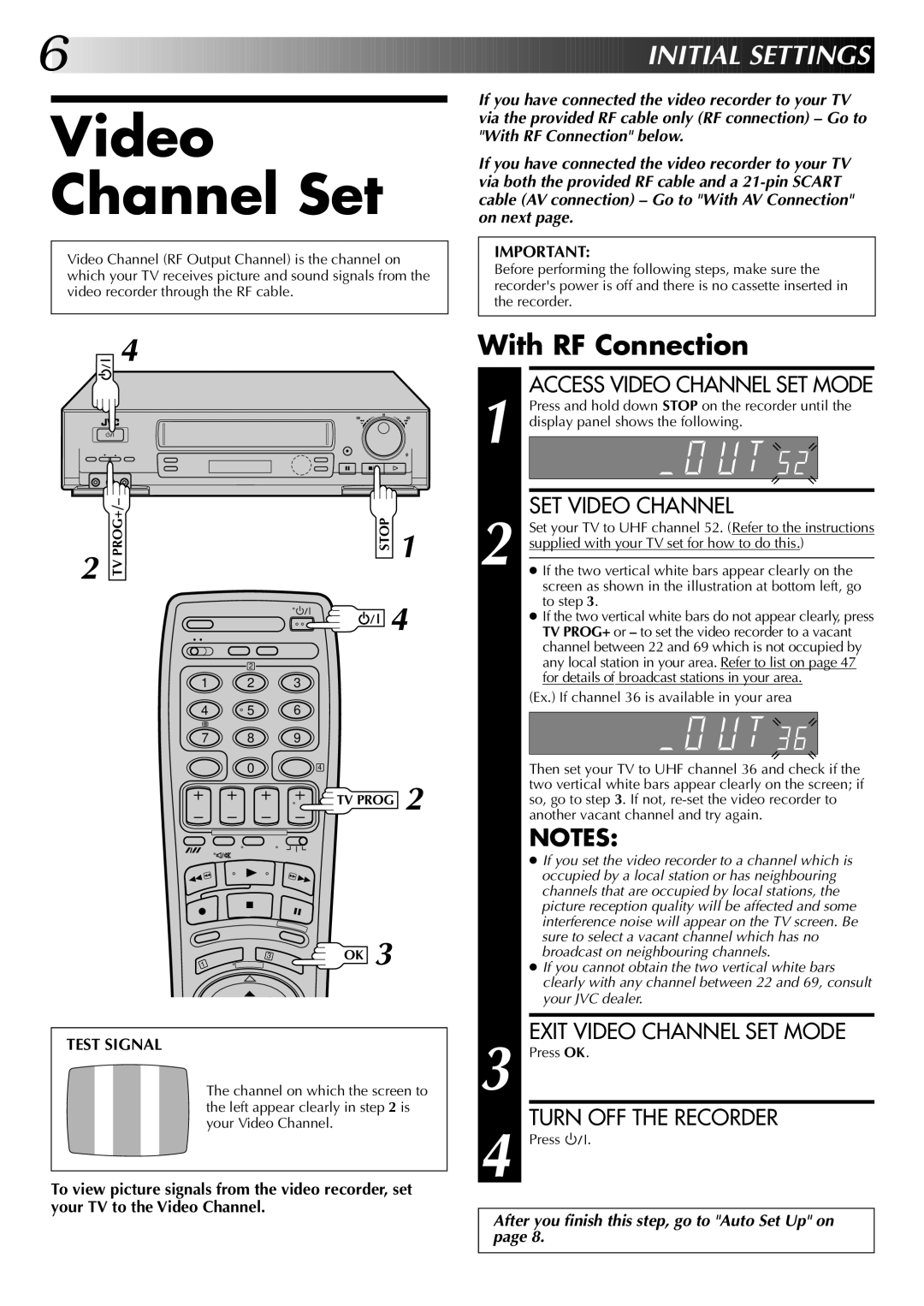
4 | With RF Connection | |
|
|
|
| ACCESS VIDEO CHANNEL SET MODE |
| Press and hold down STOP on the recorder until the |
q | 1 display panel shows the following. |
2 |
|
|
| STOP | 1 | SET VIDEO CHANNEL | ||
|
|
| 2 ● If the two vertical white bars appear clearly on the | |||||
|
|
|
|
|
|
| Set your TV to UHF channel 52. (Refer to the instructions | |
|
|
|
|
|
|
| supplied with your TV set for how to do this.) | |
|
|
|
|
|
|
| screen as shown in the illustration at bottom left, go | |
|
|
|
|
| 4 | to step 3. | ||
|
|
|
|
| ● If the two vertical white bars do not appear clearly, press | |||
|
|
|
|
| TV PROG+ or – to set the video recorder to a vacant | |||
|
|
|
|
|
|
| channel between 22 and 69 which is not occupied by | |
|
| 2 |
|
|
|
| any local station in your area. Refer to list on page 47 | |
| 1 | 2 | 3 |
|
|
| for details of broadcast stations in your area. | |
|
|
|
| (Ex.) If channel 36 is available in your area | ||||
| 4 | 5 | 6 |
|
|
| ||
|
|
|
|
|
| |||
| 7 | 8 | 9 |
|
|
|
|
|
|
| 0 | 4 |
|
|
| Then set your TV to UHF channel 36 and check if the | |
|
|
|
|
|
| 2 | two vertical white bars appear clearly on the screen; if | |
|
|
|
| TV PROG | so, go to step 3. If not, | |||
|
|
|
|
|
|
| another vacant channel and try again. | |
|
|
|
|
|
|
| NOTES: | |
|
|
|
|
|
|
| ● If you set the video recorder to a channel which is | |
|
|
|
|
|
|
| occupied by a local station or has neighbouring | |
|
|
|
|
|
|
| channels that are occupied by local stations, the | |
|
|
|
|
|
|
| picture reception quality will be affected and some | |
|
|
|
|
|
|
| interference noise will appear on the TV screen. Be | |
|
|
|
|
| 3 |
| sure to select a vacant channel which has no | |
|
|
| 3 | OK |
| broadcast on neighbouring channels. | ||
| 1 |
|
|
| ● If you cannot obtain the two vertical white bars | |||
|
|
|
|
|
|
| clearly with any channel between 22 and 69, consult | |
|
|
|
|
|
|
| your JVC dealer. | |
TEST SIGNAL |
|
|
|
|
| EXIT VIDEO CHANNEL SET MODE | ||
|
|
|
|
| 3 Press OK. | |||
| The channel on which the screen to | |||||||
| the left appear clearly in step 2 is | TURN OFF THE RECORDER | ||||||
| your Video Channel. |
|
|
| ||||
|
|
|
|
|
|
| 4 Press | . |
To view picture signals from the video recorder, set your TV to the Video Channel.