![]()
![]()
![]()
![]()
![]()
![]()
![]()
![]()
![]()
![]()
![]()
![]()
![]()
![]()
![]()
![]()
![]()
![]()
![]()
![]()
![]()
![]()
![]()
![]()
![]()
![]() 61
61![]()
REAR VIEW
1 | 2 | 3 | 4 | 5 | 6 |
|
|
|
|
| ANT. IN |
|
| AV1 OUT | AV1 IN/OUT |
|
|
| S OUT |
| R L |
| |
|
| COMP. Y/C |
| AUDIO OUT |
|
|
|
|
|
| |
|
|
|
| JLIP |
|
|
|
|
| RF OUT | |
|
|
| AV2 IN |
|
|
|
|
|
| PAUSE/ |
|
|
|
|
| R.A. EDIT |
|
|
|
| 7 | 8 | 9 0 |
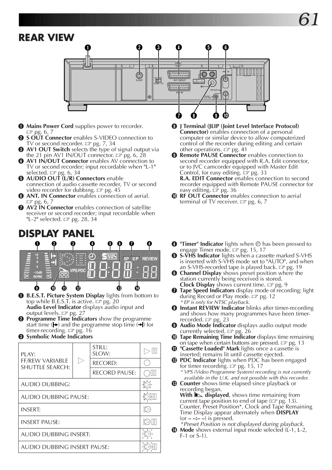
1Mains Power Cord supplies power to recorder. ☞ pg. 6, 7
2S OUT Connector enables
3AV1 OUT Switch selects the type of signal output via the 21 pin AV1 IN/OUT connector. ☞ pg. 6, 28
4AV1 IN/OUT Connector enables AV connection to TV or second recorder; input recordable when
5AUDIO OUT (L/R) Connectors enable
connection of audio cassette recorder, TV or second video recorder for dubbing. ☞ pg. 45
6ANT. IN Connector enables connection of aerial. ☞ pg. 6, 7
7AV2 IN Connector enables connection of satellite receiver or second recorder; input recordable when
8J Terminal (JLIP (Joint Level Interface Protocol) Connector) enables connection of a personal computer or similar device to allow computerized control of the recorder during editing and certain other operations. ☞ pg. 41
9Remote PAUSE Connector enables connection to second recorder equipped with R.A. Edit connector, or to JVC camcorder equipped with Master Edit Control, for easy editing. ☞ pg. 33
R.A. EDIT Connector enables connection to second recorder equipped with Remote PAUSE connector for easy editing. ☞ pg. 36
0RF OUT Connector enables connection to aerial terminal of TV receiver. ☞ pg. 6, 7
DISPLAY PANEL
1 | 2 |
| 3 | 4 | 5 6 | 7 | 8 |
+8 |
|
|
|
|
|
|
|
4 |
|
|
|
|
| SP | REVIEW |
0 |
|
|
|
|
|
|
|
6 |
|
| VPS/PDC |
|
|
|
|
15dB |
|
|
|
|
|
| |
|
|
|
|
|
|
| |
NORM |
|
|
|
|
|
|
|
9 | 0 | ! | @ |
| # |
| $ |
1B.E.S.T. Picture System Display lights from bottom to top while B.E.S.T. is active. ☞ pg. 20
Audio Level Indicator displays audio input and output levels. ☞ pg. 27
2Programme Time Indicators show the programme start time (![]() ) and the programme stop time (
) and the programme stop time (![]()
![]() ) for
) for
3Symbolic Mode Indicators
|
| STILL: |
PLAY: |
| SLOW: |
FF/REW VARIABLE |
| RECORD: |
SHUTTLE SEARCH: |
| |
|
| |
| RECORD PAUSE: | |
|
| |
|
|
|
AUDIO DUBBING: |
|
|
AUDIO DUBBING PAUSE:
INSERT:
INSERT PAUSE:
AUDIO DUBBING INSERT:
AUDIO DUBBING INSERT PAUSE:
4"Timer" Indicator lights when ähas been pressed to
engage Timer mode. ☞ pg. 15, 17
5
6Channel Display shows preset position where the station currently being received is stored.
Clock Display shows current time. ☞ pg. 9
7Tape Speed Indicators display mode of recording; light during Record or Play mode. ☞ pg. 12
*EP is only for NTSC playback.
8Instant REVIEW Indicator blinks after
9Audio Mode Indicator displays audio output mode currently selected. ☞ pg. 26
0Tape Remaining Time Indicator displays time remaining on tape when certain buttons are pressed. ☞ pg. 13
!"Cassette Loaded" Mark lights once a cassette is inserted; remains lit until cassette ejected.
@PDC Indicator lights when PDC has been engaged for timer recording. ☞ pg. 15, 17
*VPS (Video Programme System) recording is not currently available in the U.K. and not possible with this recorder.
#Counter shows time elapsed since playback or recording began.
With ![]() displayed, shows time remaining from current tape position to end of tape (☞ pg. 13). Counter, Preset Position*, Clock and Tape Remaining Time Display appear alternately when DISPLAY
displayed, shows time remaining from current tape position to end of tape (☞ pg. 13). Counter, Preset Position*, Clock and Tape Remaining Time Display appear alternately when DISPLAY
(or – –:– –) is pressed.
*Preset Position is not displayed during playback. $ Mode shows external input mode selected