Description of Terminals (continued)
English
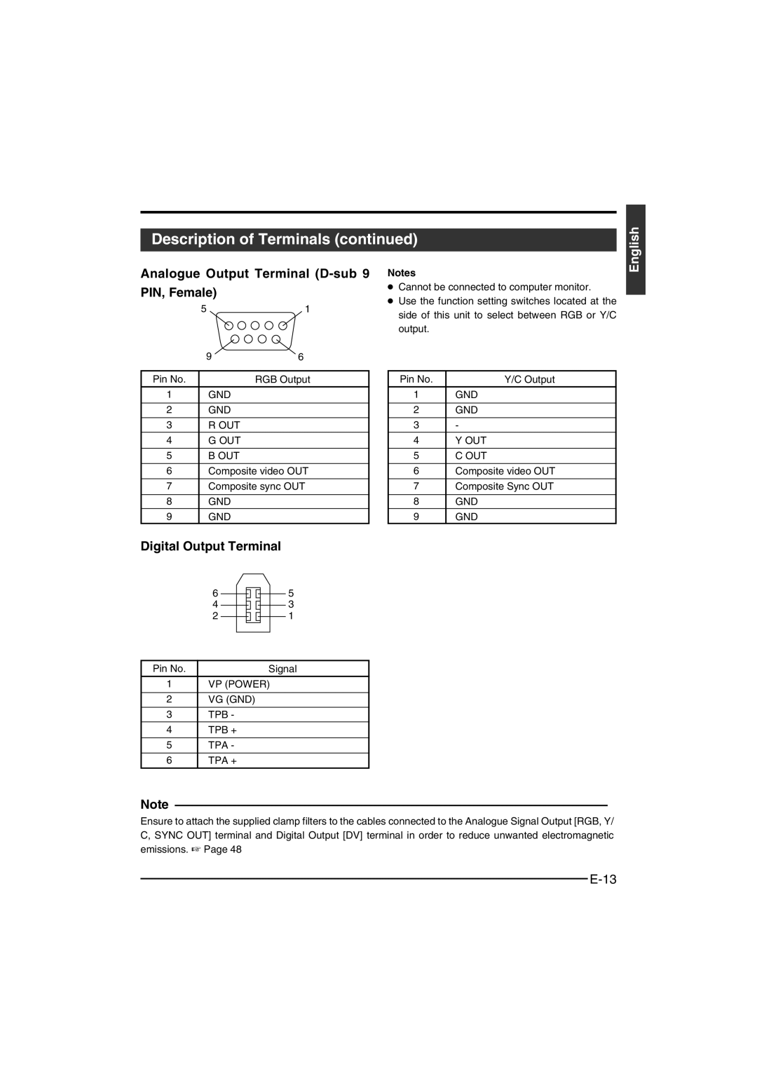
Analogue Output Terminal (D-sub 9
PIN, Female)
51
| 9 | 6 |
|
|
|
Pin No. |
| RGB Output |
1 | GND |
|
|
|
|
2 | GND |
|
|
|
|
3 | R OUT |
|
4 | G OUT |
|
|
|
|
5 | B OUT |
|
|
| |
6 | Composite video OUT | |
|
| |
7 | Composite sync OUT | |
|
|
|
8 | GND |
|
9 | GND |
|
Digital Output Terminal
Notes
●Cannot be connected to computer monitor.
●Use the function setting switches located at the side of this unit to select between RGB or Y/C output.
Pin No. | Y/C Output |
1 | GND |
|
|
2 | GND |
|
|
3 | - |
4 | Y OUT |
|
|
5 | C OUT |
|
|
6 | Composite video OUT |
|
|
7 | Composite Sync OUT |
|
|
8 | GND |
9 | GND |
6 |
|
|
| 5 |
|
| |||
4 |
|
|
| 3 |
|
| |||
2 |
|
| 1 | |
| ||||
Pin No. | Signal |
1 | VP (POWER) |
|
|
2 | VG (GND) |
|
|
3 | TPB - |
4 | TPB + |
|
|
5 | TPA - |
|
|
6 | TPA + |
Note
Ensure to attach the supplied clamp filters to the cables connected to the Analogue Signal Output [RGB, Y/ C, SYNC OUT] terminal and Digital Output [DV] terminal in order to reduce unwanted electromagnetic emissions. ☞ Page 48