RX-8022PSL
Page
RX-8022PSL
Table of Contents
Introduction
Features Precautions
Front Panel
Master Volume control
Display Window
STANDBY/ON button and Standby lamp Speakers ON/OFF 1 button
Remote control display window
Remote Control
Connecting the FM and AM Antennas
Before Installation
Checking the Supplied Accessories
Setting the Voltage Selector
AM Antenna Connections
Connecting the Speakers
Best reception
Typical speaker layout
Connecting the front, center and surround speakers
Basic connecting procedure
Connecting the surround back speakers
Connecting the subwoofer speaker
Enhancing your audio system
Connecting Audio/Video Components
Analog Connections
Audio component connections
To audio output
CD player
Cassette deck or MD recorder
CD recorder To audio input
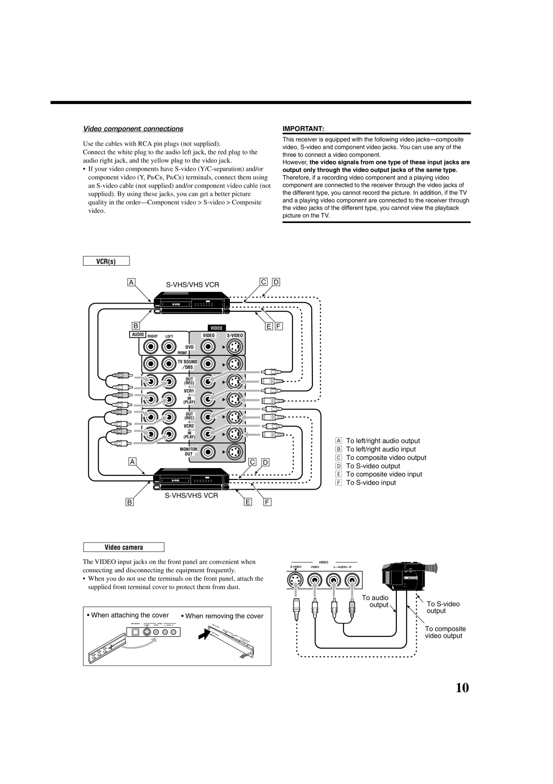
Video component connections
When attaching the cover
VCRs
VHS/VHS VCR
DBS tuner
TV and/or DBS tuner
DVD player
When you connect a DVD player with stereo output jacks
DVD player
Digital input terminals
Digital Connections
Digital output terminal
USB Connection
Change the PC audio setting
Lamp on the USB Audio button on the front panel lights up
USB cable not supplied
Putting Batteries in the Remote Control
Connecting the Power Cord
Plug the power cord into an AC outlet
Replace the cover
Before using the remote control
Turning On the Power
Basic Operations
Selecting the Source to Play
Speaker indicators light up
Speaker and signal indicators on the display
Changing the source name
Selecting different sources for picture and sound
Headphone mode
Adjusting the Volume Listening Only with Headphones
Selecting the Front Speakers
When selecting Dgtl D.D
Selecting the Analog or Digital Input Mode
When selecting Dgtl DTS
Dgtl Auto appears on the display
Basic adjustment auto memory
Using the Sleep Timer
Muting the Sound
Changing the Display Brightness
Basic Procedure
Basic Settings
Setting the Speakers
Measuring unit-DIST Unit
Setting the Speaker Distance
Feet Select this to set the distance in feet
Speaker distance-FRONT DIST, Center Cntr
Setting the Dynamic Range-MID Night
Setting the Bass Sounds
Crossover frequency-CROSSOVER
Low frequency effect attenuator-LFE ATT
Setting the Component Video Input
Setting the Digital Input Digital in Terminals
Digital in 1-DVD, MD**, CDR, TV or DBS* or CD
To recall the volume level
Select this not to store the volume level
To cancel the One Touch Operation
Source name and Surround/DSP mode appear
Receiving Radio Broadcasts
Tuning into Stations Manually Using Preset Tuning
Selecting the FM Reception Mode
Press FM/AM Preset 5 or ∞
While listening to an FM station, press FM Mode
To tune in a preset station
Press 5 or ∞ to move to an item you want to set or adjust
Operating the Tuner Using the On-Screen Display
Storing the preset stations
Press 5 or ∞ to move to Tuner CONTROL, then press 2 or
Attenuating the Input Signal
Setting Sound
Turning Analog Direct On and Off
Press Bass Boost to turn on Bass Bass Boost Boost function
Reinforcing the Bass
Press Sound
Press Bass Boost to turn on Bass
Reproducing Theater Ambience Introducing the Surround Modes
Using Surround Modes and DSP Modes
Dolby Surround
Movie theater At home
DTS Digital Surround
DVD Multi Playback Mode
Neo6 Music
DTS-ES
Behind
3D Headphone Mode
Early reflections
Direct sounds
Dolby Digital 5.1-channel software
Dolby Digital EX software Dolby D EX
DTS-ES software
DTS 5.1-channel software DTS
On the front panel From the remote control
Press Surround to activate Surround mode
Activating the Surround Modes
Activating the DSP Modes
Activating the DVD Multi Playback Mode
Using the DVD Multi Playback Mode
Press DVD Multi so that DVD Multi appears on the display
Adjusting Sound
Adjusting the Equalization Patterns
Select this to adjust the subwoofer
Adjusting the Speaker Output Levels
Level
Output level
Press Level + or to adjust Speaker output level -10 dB to
Select a speaker you want to adjust
Press Level Adjust repeatedly to
Down ∞ to adjust the speaker
Parameter you want to adjust
Show Effect Adjust menu see
Down ∞ to adjust the sound
Press Effect repeatedly to select a
Same time
Compu Link Remote Control System
Press the play 3 button on the CD player
Connections
Text Compu Link Remote Control System
Functions
Press Text Display while CD or MD is selected as the source
On-Screen Operating buttons on the remote control
Operations
Showing the Disc Information on the TV Screen
Press SET
Press Text Display while CD is selected as the source
Then press SET
Press SET again
Press 5 or ∞ to move To GENRE, then Press SET
Press 5 or ∞ to move To SEARCH, then Press SET
Entering the Disc Information
Enter the disc title, referring to steps 3
Press Text Display while MD is selected as the source
Press 5 or ∞ to move to the genre you want, then press SET
Connections 1 AV Compu Link Connection
AV Compu Link Remote Control System
Connections 2 Video Cable Connection
VCR connected to
Automatic Power On/Off
Automatic Selection of TV’s Input Mode
One-Touch Video Play
One-Touch DVD Play
Operating Audio Components
Operating JVC’s Audio/Video Components
Tuner
Sound control section Amplifier
CD changer
CD player
Turntable
CD recorder
VCR 1 VCR connected to the VCR 1 jacks
Operating Video Components
DVD player
Operating Other Manufacturers’ Video Equipment
Enter a manufacturer’s code using buttons 1-9,
Press and hold TV Press TV/DBS
Release TV
Press and hold CATV/DBS Press CATV/DBS Control
Enter manufacturer’s code using buttons 1-9,
Release CATV/DBS
Press and hold VCR1 Press VCR1
Release Audio
Press and hold Audio Press DVD
Problem Possible Cause Solution
Troubleshooting
Problem
Amplifier
Specifications
Audio
Video
FM tuner IHF
Tuning Range Usable Sensitivity Signal-to-Noise Ratio
AM tuner
General
Electric shock