LVT1002-001B
RX-ES1SL XV-N55SL
If in Doubt Consult a Competent Electrician
Reproduction of Labels
Important for Laser Products
XV-N55SL
RX-ES1SL
Do not stack XV-N55SL and RX-ES1SL
Above ALL
Table of Contents
When operating the receiver RX-ES1SL, set the mode
Remote control
When operating the player XV-N55SL, set the mode
Selector h to AUDIO/TV/VCR/STB
Front panel
Parts identification
Rear panel
Display window
Display window
AV OUT Video Signal Selector
Front panel
COAXIAL, Optical
Checking the supplied accessories
Precautions
Putting batteries in the remote control
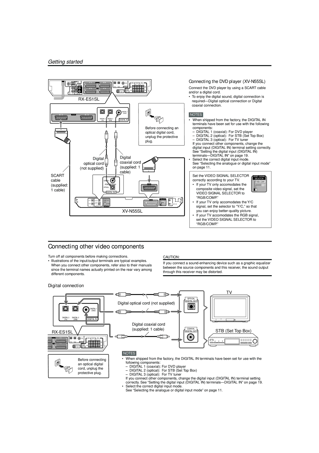
Getting started
Getting started
Connecting the FM and AM MW antennas
FM antenna connection
FM antenna supplied
Speaker Layout Diagram
Connecting the speakers and DVD player
Connecting the subwoofer
Connecting the front, center, and surround speakers
Connecting the DVD player XV-N55SL
Connecting other video components
Digital connection
STB Set Top Box
Scart connection
Analogue connection for DVD Multi playback see
Connecting the power cord
Monaural
DVD Multi playback is not available for XV-N55SL
To turn off the power into standby
Turn on the power
Selecting the analogue or digital input mode
Basic operations
Selecting the digital decode mode
Adjust the volume
Listening with headphones
Basic operations
To restore the sound, press Muting again
To cancel TV Direct and turn off the receiver, press
Activating TV Direct
Turning off the sounds temporarily- Muting
Basic adjustment of auto memory
Turning off the power with the Sleep Timer
Signal and speaker indicators on the display
Changing the display brightness
From the remote control only
Speaker settings
TV/VCR/STB
Speaker settings
Operating procedure
Setting the speakers size
When selecting Medium Room
When selecting Large Room
Setting the crossover frequency-CROSS
Setting the speaker delay time
Setting the low frequency effect attenuator -LFE
Setting the dynamic range compression -D.COMP
Operating procedure
Basic settings
Digital 3DVD player Initial setting
Digital 2STB
Setting the Auto Function mode-MODE
Setting Auto Surround-AUTO SR
Basic settings
Adjusting the tone-BASS, Treble
Sound adjustments
Adjusting the subwoofer output level
Press Adjust
Attenuating the input signal-ATT
Adjusting the front speakers output balance-BAL
Sound adjustments
Setting the subwoofer audio position
Using preset tuning
Tuning in to stations manually
To store the preset stations
Tuner operations
To tune in a preset station
Selecting the FM reception mode
Tuner operations
What information can RDS signals provide?
Using the RDS Radio Data System to receive FM stations
Press Display while listening to an FM station
Frequency RT Normal indication
Description of the PTY codes
To search for a program using the PTY codes
Press PTY Search while listening to an FM station
PTY codes
None TA/NEWS/INFO NEWS/INFO
Switching to broadcast program of your choice temporarily
TA Traffic Announcement in your area
News News
Reproducing theater ambience
Creating realistic sound fields
Introducing the Surround/DSP modes
Surround modes
Available Surround/DSP modes for each input signal
DSP Digital Signal Processor modes
Creating realistic sound fields
DAP Digital Acoustic Processor modes
Dolby D or DTS Stereo Surround/DSP off
Using Surround modes
Press Test to check the speakers output balance
Turn Multi JOG to select a appropriate surround mode
Press Test again to stop the test tone
Select and play software you like Press Surround
Repeat steps 5 and 6 to adjust the other settings
Using DSP modes
Always set the mode selector to AUDIO/TV/VCR/STB
To cancel Surround mode
To cancel DSP Modes
To adjust the DAP effect level
Effect available only for DAP modes *2
Adjusting the speaker output level
Using the DVD Multi playback mode
From the remote control Press DVD Multi
Turn Source Selector until DVD Multi appears on the display
About this manual
Before operation
About discs
Turning on/off the player
Initial setup
Basic playback
To bring up the DVD Player SET UP display later
If a menu is shown on the TV screen
About PBC Playback Control
Resuming playback
Various speed playback
Locating the beginning of a scene or song
Using the numeric buttons
To replay the previous scenes One touch replay function
Playing from a specific position
Advanced operations
Locating a desired scene from the DVD menu
Specifying a desired title
To play back in a specific order Program play
Changing the playback order
Advanced operations
To dismiss the menu bar
To play back in random order Random play
To repeat a desired part A-B repeat playback
Repeat playback
To stop repeat playback
To quit repeat playback
To change the audio language or sound Audio
Changing the language, sound and scene angle
To select a scene angle of DVD Video Angle
Special picture/sound effect
To adjust the picture character VFP
To zoom in pictures
To return to the normal playback
Menu bar functions
Basic operation procedure
To simulate surround sound 3D Phonic
To bring up the menu bar
Menu bar functions for DVD Video
Time mode selection
Menu bar functions for SVCD/Video CD/ Audio CD
CHAP. Chapter search
Operations
MP3/WMA disc playback
About MP3/WMA discs
Basic operations
Direct selection
Repeat playback
MP3/WMA disc playback
About Jpeg discs
Jpeg disc playback
Basic operations
To see a desired picture
To zoom in the picture
Viewing pictures continuously slide show mode
To start the slide show
To select the start point of the slide show
Repeat function
Press Repeat mode remains active
While the Jpeg Control display is shown, press Repeat
Press 3 to start repeat playback
How to set preferences
Changing the initial settings
Selecting preferences
About the Preference display
Language menu
Changing the initial settings
Picture menu
Others menu
Audio menu
To set Parental Lock for the first time
Limiting playback by children
Bring up the Others menu
Press 5/∞ to move To select Parental Lock then press Enter
To temporarily release the Parental Lock
To change the settings
Press 5/∞ to move To select Parental Lock and press Enter
Press 5/∞ to move to Temporary RELEASE, then press Enter
Additional information
Appendix a Country/Area code list for Parental Lock
For pages 45
Appendix C Digital output signal chart
For
Output Disc type
Appendix D Glossary
DVD player
Operating other JVC products
Operating other manufacturers’ equipment
Changing the transmittable signals for operating an
Try to operate your STB by pressing STB
Manufacturer Codes
Changing the transmittable signals for operating a
Changing the transmittable signals for operating a
Operating other manufacturers’ equipment
Try to operate your VCR by pressing VCR
Problem Possible Cause Solution
Troubleshooting
General
FM/AM Problem Possible Cause Solution
Troubleshooting
Surround/DSP
RGB/COMP
Video Active
Standard
Operation Picture Audio
Amplifier
Specifications
FM tuner IHF
AM MW tuner
Audio characteristics
Specifications
Other
Video outputs
2003 Victor Company of JAPAN, Limited 0203NHMMDWJEIN