29
30
Output Aspect Ratio Control
There are ve controls for Output Aspect Ratio (OAR):
Display Aspect Ratio
Lens Mode
Screen Aspect Ratio
Image Shift
Underscan
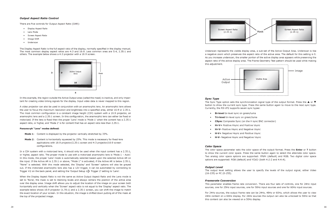
The Display Aspect Ratio is the full aspect ratio of the display, normally specied in the display manual.
The most common display aspect ratios are 4:3 and 16:9. Less common ones are 5:4, 2.35:1 and
others. The example below shows a 4:3 projector with a 16:9 screen.
In this example, the region outside the Active Output area (called the mask) is inactive, and only impor-
tant for creating video timing signals for the display. Input video data is never mapped to this region.
A video projector can also be used in conjunction with an anamorphic lens. An anamorphic lens allows
the user to focus the maximum resolution and brightness into a specied area, either 16:9 or 2.35:1.
The most common conguration is a constant image height (CIH) system with a 16:9 projector, an
anamorphic lens and a 2.35:1 screen. In this conguration, the anamorphic lens can either be xed or
motorized. If the lens is xed then the proper ‘Lens’ mode is ‘Mode 1’ when the content has a 2.35:1
aspect ratio, or higher, and ‘Mode 2’ is for content that has an aspect ratio less than 2.35:1.
Panamorph “Lens” modes dened:
Mode 1: Content is displayed by the projector vertically stretched by 33%.
Mode 2: Content is horizontally squeezed by 25%. This mode is necessary for xed-lens
applications with 16:9 projector/2.35:1 screen and 4:3 projector/16:9 screen
congurations.
In a CIH system with a motorized lens, it should only be used when the input content has a 2.35:1,
or higher, aspect ratio. The proper mode to use with a motorized anamorphic lens is ‘Mode 1 – Auto’.
in this mode, the proper ‘lens’ mode is automatically selected based upon the selected active ar on
the input. If the Active AR is 2.35:1 or above, “Mode 1” is activated, if the Active AR is below 2.35:1,
“None” is selected. With this mode selected, the ‘Display’ and ‘Screen’ options will also be grayed
out. If the motorized anamorphic lens also has a 12V trigger, it can be automated by connecting to
Trigger #2 on the back panel, and setting the ‘Output Setup _ Trigger 2’ setting to ‘Lens’.
When the display aspect ratio is not the same as active output aspect ratio and the lens mode is
set to ‘none’, the mask is set to blanking levels and always centers the position of the active area
over the display area. Image shift allows you to adjust the location of the image on your screen both
horizontally and vertically when the ‘Screen’ aspect ratio is not equal to the ‘Display’ aspect ratio. The
example below shows 16:9 projector (1.78:1) and a 2.35:1 screen, you can shift the image to match
the exact location of your screen. In this situation, the image is shifted down putting all of the mask at
the top of the projected image.
Underscan represents the visible display area, a sub-set of the Active Output Area. Underscan is like
a negative zoom which preserves the aspect ratio of the active area. The default for this setting is 0.
as you increase underscan, the smaller portion of the active display area appears while preserving the
aspect ratio of the active display area. The Frame Geometry Test pattern should be used while making
this adjustment.
Sync Type
The Sync Type option sets the synchronization signal type of the output format. Press the p or q
button to show the current sync type. Press the same button again to move to the next sync type.
Currently, the rs-Vp2 supports seven sync types:
Bi-level bi-level sync on green/luma
Tri-level tri-level sync on green/luma
CSync Composite Sync (on the H sync BNC connector)
H+V+ positive Hsync and positive Vsync
H+V- positive Hsync and negative Vsync
H-V+ negative Hsync and positive Vsync
H-V- negative Hsync and negative Vsync
Color Space
The color space parameter sets the color space of the output format. Press the Enter or ? button
to show the current color space. Press the same button again to select the alternate color space.
Two analog color space options are supported: YPbPr (default) and RGB. Two digital color space
options are supported: RGB (default) and YCbCr (both 4:2:2 and 4:4:4).
Output Level
The output level setting allows the user to specify the levels of the output signal, either Video
(16-235) or PC (0-255).
Framerate Conversion
This parameter enables frame rate conversion. There are four sets of controls, one for 24Hz input
sources, one for 25Hz input sources, one for 50Hz input sources and one for 60Hz input sources.
For 24Hz sources, the output frame rate can be 24Hz, 48Hz or 60Hz, which allows the user to view
24Hz content on a 60Hz display. For 24Hz sources the output can also be unlocked to 50Hz so that
this content can also be viewed on a 50Hz display.
Borders
Active Input
Area Borders
Active Input
Area
Active Input
Area
Mask
Active Output
Area
16
9
Mask
Screen Aspect Ratio
(2.35:1)
Screen Aspect Ratio
(2.35:1)
Visible Area
ActiveOutput

Page 37, R2

page 38

Image
4
3
Borders
Active Input
Area Borders
Active Input
Area
Active Input
Area
Mask
Active Output
Area
16
9
Mask
Screen Aspect Ratio
(2.35:1)
Screen Aspect Ratio
(2.35:1)
Visible Area
ActiveOutput

Page 37, R2

page 38

Image
4
3
Borders
Active Input
Area Borders
Active Input
Area
Active Input
Area
Mask
Active Output
Area
16
9
Mask
Screen Aspect Ratio
(2.35:1)
Screen Aspect Ratio
(2.35:1)
Visible Area
Active
Output
Page 37, R2page 38
Image
4
3