These modes can be recalled using the Viewing Modes button on the remote control.
There are also three additional modes which can be saved by a Imaging Science Foundation certified calibrator. These calibrators have been trained on proper display calibration methodology. More information about the ISF is available at www.imagingscience.com.
Gamut
The RS-VP2 has the ability to output a SMPTE-C (REC 601) color gamut from both the RS1 and the RS2. The native color gamut on these projectors provides a gamut that is wider than the gamut of the current content. There are three options in this submenu:
•Wide
•RS1
•RS2
When ‘Wide’ is selected there is no change made to color gamut. When ‘RS1’ is selected, the color gamut is automatically adjusted so that a connected RS1 projector outputs a SMPTE-C color gamut. When ‘RS2’ is selected, the color gamut is automatically adjusted so that a connected RS2 projector outputs a SMPTE-C color gamut.
HDCP Mode
There are two HDCP modes:
•Off: HDCP is disabled at the RS-VP2’s HDMI output.
•On: The RS-VP2 continuously looks for a HDCP display device on its HDMI output. This is the default setting.
NOTE: The RS-VP2 is not designed to remove HDCP from a protected signal. If this setting is set to ‘On’ make sure that the corresponding HDCP Mode setting on the input is also set to ‘On’.
12V Triggers
The two 12-volt trigger ports are designed to supply a combined total of 500mA which is split between the two devices based on their draw, so one device can draw up to 495mA if the other only draws 5mA — or both can draw 250mA. These devices do not need to have the same current draw to work. This is enough current to drive one or two 12-volt relays, suitable for turning on a lens and projector, for example. If the combined draw exceeds 500mA, the video processor is protected against overload. The state of the 12V triggers can individually be adjusted in the ‘Configuration’ menu. This is helpful if the default state of the connected device is incorrect. For example a screen may be set to go up, when in fact the desired state for the screen is to be down.
When the Trigger Level is set to “Normal”, it will supply +12vdc on the TIP when active, and will pull the TIP to Ground (0vdc), referenced to the SHIELD — when inactive. When the trigger port is set to “Negative”, it will pull the TIP to Ground (0vdc), referenced to SHIELD — and will supply +12vdc to the TIP when inactive. The SHEILD will never carry the +12vdc supply signal. To ensure that damage is not caused, please check the manual of the device that you intend on connecting to the RS-VP2 before inserting the trigger plug into the jack.
Trigger #1 is powered on when the RS-VP2 is powered on. Trigger #1 is powered off when
the RS-VP2 is put into Standby mode. This can be useful for powering on a display or motor- izing a screen or lift.
Trigger #2 can be programmed to be powered on in the ‘Output Setup’ menu. This action can be saved as part of a Display Profile. The ‘Lens’ option facilitates use of an anamorphic lens.
Installer Note: The trigger ports are outputs and are not designed to directly receive a 12-volt trigger signal from another device, like an amplifier, automation controller or 12-volt power supply. Care has been taken in the design to ensure that if this was done, no harm should come to the video processor – but it is strongly recommend that other devices are checked to ensure that the trigger ports on the RS-VP2 are not being “back-fed”.
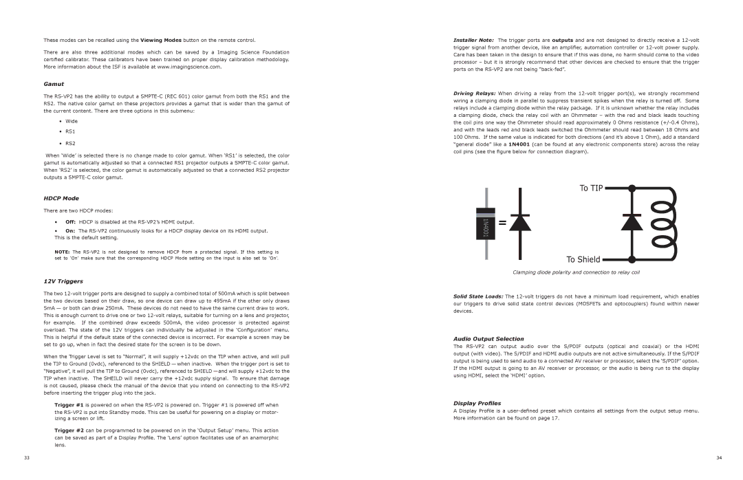
Driving Relays: When driving a relay from the 12-volt trigger port(s), we strongly recommend wiring a clamping diode in parallel to suppress transient spikes when the relay is turned off. Some relays include a clamping diode within the relay package. If it is unknown whether the relay includes a clamping diode, check the relay coil with an Ohmmeter – with the red and black leads touching the coil pins one way the Ohmmeter should read approximately 0 Ohms resistance (+/-0.4 Ohms), and with the leads red and black leads switched the Ohmmeter should read between 18 Ohms and 100 Ohms. If the same value is indicated for both directions (and it’s above 1 Ohm), add a standard “general diode” like a 1N4001 (can be found at any electronic components store) across the relay coil pins (see the figure below for connection diagram).
Clamping diode polarity and connection to relay coil
Solid State Loads: The 12-volt triggers do not have a minimum load requirement, which enables our triggers to drive solid state control devices (MOSFETs and optocouplers) found within newer devices.
Audio Output Selection
The RS-VP2 can output audio over the S/PDIF outputs (optical and coaxial) or the HDMI output (with video). The S/PDIF and HDMI audio outputs are not active simultaneously. If the S/PDIF output is being used to send audio to a connected AV receiver or processor, select the ‘S/PDIF’ option. If the HDMI output is going to an AV receiver or processor, or the audio is being run to the display using HDMI, select the ‘HDMI’ option.
Display Profiles
A Display Profile is a user-defined preset which contains all settings from the output setup menu. More information can be found on page 17.