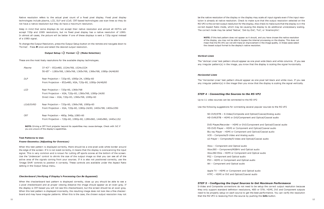
Native resolution refers to the actual pixel count of a fixed pixel display. Fixed pixel display technologies include plasma, LCD, DLP and LCoS. CRT-based technologies use scan lines so they do not have a native resolution but they do have a maximum resolution.
Keep in mind that some displays do not accept their native resolution and almost all HDTVs will accept 720p and 1080i resolutions, but no fixed pixel display has a native resolution of 1080i. In almost all cases, the picture will be better if one of these displays is sent a 720p signal instead of a 1080i signal.
To change the Output Resolution, press the Output Setup button on the remote and navigate down to ‘Format’. Press uonce and select the desired output resolution.
Output Setup _Format _(Make Selection)
These are the most likely resolutions for the available display technologies.
Plasma | 37-43” – 852x480, 1024x768, 1024x1024 |
| 50-65” – 1280x768, 1360x768, 1365x768, 1366x768, 1080p-24/48/60 |
DLP | rear Projection – 720p-60, 1080p-24, 1080p-60 |
| Front Projection – 852x480, XGA, 720p-60, 1080p-24/48/60 |
LCD | rear Projection – 720p-60, 1366x768 |
| Front Projection – XGA, 720p-60, 1366x768, 1080p-24/60 |
| Direct View – XGA, 720p-60, 1366x768, 1080p-60 |
LCoS/SXRD | Rear Projection – 720p-60, 1366x768, 1080p-60 |
| Front Projection – XGA, 720p-60, 1080p-24/60, 1400x788, 1400x1050 |
CRT | rear Projection – 480p, 540p, 1080i-60 |
| front Projection – 720p-60, 1080p-60, 1280x960, 1440x960, 1440x1152 |
NOTE: Driving a CRT front projector beyond its capabilities may cause damage. Check with JVC if you are unsure of the display’s capabilities.
Test Patterns to Use:
Frame Geometry (Adjusting for Overscan)
When this test pattern is displayed correctly, there should be a one-pixel wide white border around the edge of the screen: If it is not sized correctly, it means that the display is overscanning the input signal. This is very common and is known for cutting off sports scores at the bottom of the screen. Use the ‘Underscan’ control to shrink the size of the output image so that you can see all of the active area of the signals coming from your sources. If it is also not positioned correctly, use the ‘Image Shift’ controls to position it correctly. These controls are available under the Aspect Ratio setting in the Output Setup menu.
Checkerboard (Verifying if Display’s Processing Can Be Bypassed)
When the checkerboard test pattern is displayed correctly, close up you should be able to see a 1-pixel checkerboard and at proper viewing distance the image should appear as an even gray. If the display is CRT-based you will not see this checkerboard, but the screen should be an even gray. When this test pattern is displayed incorrectly, the resulting image does not look like a fine checker- board and may have irregular patterns. When this is the case, the chosen output resolution may not
be the native resolution of the display or the display may scale all input signals even if the input reso- lution is already at native resolution. Check to make sure that the output resolution selected on the RS-VP2 is the correct output resolution for the display. Also check to make sure that the display is in the correct Aspect Ratio mode, which may be causing the display to do additional unnecessary scaling. The correct mode may be called ‘Native’, ‘Dot-by-Dot’, ‘Full’, or ‘Anamorphic’.
NOTE: If this test pattern does not appear as it should, and you have chosen the native resolution of the display, you may not be able to bypass the internal processing on the display. This does not mean that the RS-VP2 can not still make an improvement in the image quality. In these cases select the closest output format to the display’s native resolution.
Vertical Lines
The ‘Vertical Lines’ test pattern should appear as one pixel wide black and white columns. If you see any irregular pattern(s) in the image, you know that the display is scaling the signal horizontally.
Horizontal Lines
The ‘Horizontal Lines’ test pattern should appear as one pixel tall black and white rows. If you see any irregular pattern(s) in the image then you know that the display is scaling the signal vertically.
STEP 4 - Connecting the Sources to the RS-VP2
Up to 11 video sources can be connected to the RS-VP2
Use the following suggestions for connecting several popular sources to the RS-VP2
SD-DVR/STB – S-Video/Composite and Optical/Coaxial/Analog audio
HD-DVR/STB – HDMI or DVI/Component and Optical/Coaxial audio
DVD Player/Recorder – HDMI or DVI/Component and Optical/Coaxial audio
HD-DVD Player – HDMI or Component and Optical/Coaxial audio
Blu-ray Player - HDMI or Component and Optical/Coaxial audio
VCR – Composite/S-Video and Analog audio
LD Player – Composite/S-Video and Optical/Coaxial audio
Xbox – Component and Optical audio
Xbox360 – Component/RGBHV and Optical audio
Xbox360 Elite – HDMI or Component and Optical audio
PS2 – Component and Optical audio
PS3 – HDMI or Component and Optical audio
Wii – Component and Optical audio
Apple TV – HDMI or Component and Optical audio
HTPC – HDMI or DVI and Optical/Coaxial audio
STEP 5 - Configuring the Input Sources to Get Maximum Performance
S-Video and Composite connections do not need to be setup the correct output resolution because they only support standard definition resolutions, 480i or 576i. HDMI, DVI and Component outputs need to be properly setup on each source to get the best performance. You can verify the resolution that the RS-VP2 is receiving from the source by pushing the Info button.
