TH-A10
For U.S.A
Table of Contents
Getting Started
Checking the supplied accessories
Safety precautions
Important cautions
Rear left speaker
System outline
Center speaker SP-XCA10 Front left speaker
Front right speaker
Speaker
Installation
Adjusting the angle of the satellite speakers
To hang satellite speakers from the wall
Disc structure
About discs
Playable disc types
Video CDs with Playback Control function
AM antenna connections
Connecting the TV
Connections
FM antenna connections
To connect speakers
Connecting the rear and center speakers
Conneceting the front speakers
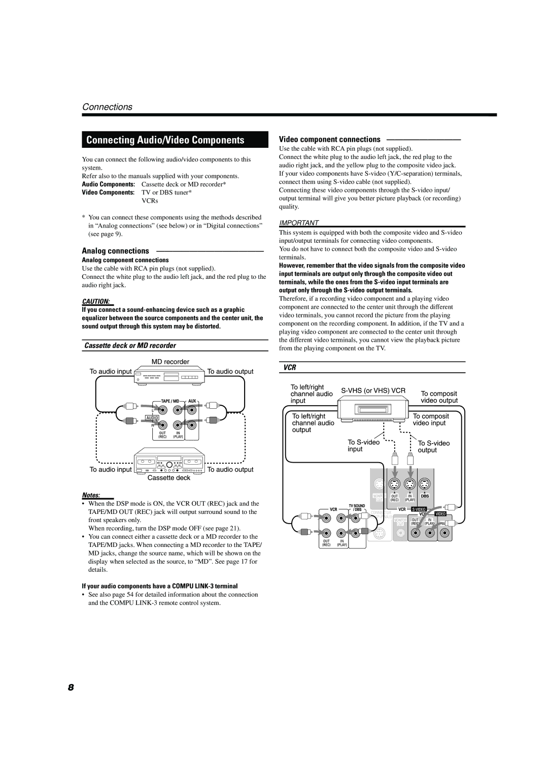
Analog component connections
Analog connections
Video component connections
If your audio components have a Compu LINK-3 terminal
Digital connections
TV sound
Plug the power cord into an AC outlet
Connecting the power cord
Light up the primary remote control buttons
Center unit Power sub-woofer
Center unit
Powered sub-woofer
Parts Identification
Display window
Remote controls
Primary remote control
Operation with the remote control
Principles of operation
On-screen menu components
To operate via the on-screen menu
Displaying the on-screen menu
Basic operation with the on-screen menu
Opening screens DVD Control display VCD Control display
On-screen menus On-screen menus for using discs
Preventing screen burn-out with Screen saver Screen Saver
For DVD
Adjusting volume
To turn the system power supply On and OFF standby
To turn TV power on and OFF
Basic operations
Changing the source name
Muting the sound
Selecting the source to play
Press one of the source selecting buttons
Selecting the analog or digital input Mode
Changing the decode mode
Sub-woofer volume control Phase setting
Adjusting the Input Signal Level
Audio channel display lamp
Using the Sleep Timer
Using the DSP Modes
When selecting DAP
Press DSP Mode
Before recording a digital source, turn off the DSP mode
Press Surround
Using the DVD player
To play a disc
Fast forward and rewind
Pausing
Locating the beginning
Press ¢or
Resuming playback
Selecting playback from the DVD menu
Press Resume during playback
Video CD menu
To specify the title or track number for Playback
To specify the time for playback
To play from the beginning of a title Chapter, or track
To specify the chapter number for Playback CHAP. Search
Press DVD on Screen
Press Digest
To select the screen for playback from Digest screen Digest
SEARCH, then press Enter
Use the number buttons 0~9 to enter the time
Hold down FF/¢or 4/REW for more than 2 seconds
To display Continuous Photos Strobe
Slow-Motion Playback Slow
Press Pause at the section you wish to view in slow motion
Zooming a scene Zoom
Changing the Subtitle Language
Use Cursor 2/3to select the desired audio language or sound
Changing the audio channel Audio
Use Cursor 5/∞to move the pointer Subutitle
Use Cursor 5/∞to move the pointer to Audio
Selecting an angle from the angle list display
Use Cursor 2/3/5/∞to select the desired angle Press Enter
Selecting a scene angle from the on-screen display
Number
Selecting the Picture Character
Or all tracks Repeat
Sampling all tracks Intro
Use Cursor 5/∞to move the pointer to
Use Cursor 5/∞to move the pointer to Time Select
Programming the Playing Order Tracks Program
Use Cursor 5/∞to move the pointer Program and press Enter
Use Cursor 5/∞to move the pointer Random
Random Play Random
Press Play to start program play
Quitting programmed playback
Tuning in stations manually
Using preset tuning
Receiving radio broadcasts
Press FM Mode
Selecting the FM reception mode
When an FM stereo broadcast is hard to receive or noisy
Beat cut
Main Menu
Performing miscellaneous settings
DVD settings on-screen display
Sound Menu Speaker Menu
Setting the Sleep Timer
Main Menu Settings
Opening the Main Menu
When the source is DVD
Changing the DSP Mode
Adjusting the volume
When the source is not DVD or Tuner
Using loudness
Sound Menu Settings
Adjusting the balance
Opening the Sound Menu
Adjusting input signal
Adjusting the DSP effect
Switching speaker mode
Speaker Menu Settings
Opening the Speaker Menu
Set speaker size
Setting speaker size
Use the 2/3cursors to select Speaker Size
Speaker parameters
Adjusting delay time
Adjusting delay time
Adjust speaker level
After adjusting speaker levels
Choosing menu language
DVD Menu Settings
Opening the DVD Menu
Change source to DVD, and stop playback
Choosing audio language
On-screen guide settings
Move the pointer to Audio Language using
Choosing subtitle language
LB Letter Box Conversion
Screen saver settings
Select monitor type
PS Pan-scan Conversion
Limiting playback by children
Enter your 4-digit password using the number buttons 0 to
To change the settings
To temporarily release the Parental lock
Care and handling of discs
How to handle discs
Maintenance of discs
Label side
Connections
AV Compu Link Remote Control System
To Video input
Remote control of the TV and VCR using this remote control
Automatic Selection of TV’s Input Mode
Automatic Power On/Off
When system power is on
Remote Control through the Remote Sensor on the center unit
Compu Link Remote Control System
Automatic Source Selection
To operate JVC’s video components using this remote control
To operate JVC’s audio components using this remote control
Operating JVC’s Audio/Video Components
VCR
Cassette deck
MD recorder
TV VOL +
Try to operate your TV by pressing TV/CATV/DBS Power
Enter manufacturer’s code three digits using buttons 1 9,
Release TV/CATV/DBS Power
10, 0, 100+ +10 Selects the channels
Try to operate your VCR by pressing VCR Power
Enter manufacturer’s code three digits using buttons 1-9,
Release VCR Power
10, 0, 100+ +10 Selects the channel
Troubleshooting
Problem Possible Cause Solution
Center unit XV-THA10
Specifications
Powered Sub-woofer SP-PWA10
Satellite Speakers SP-XSA10
Appendix a Table of languages and their abbreviations
Appendix B Country code list for parental lock
Page
HOW to Locate Your JVC Service Center
Limited Warranty Consumer Video
0200TNMNATSAN