Installation and connection
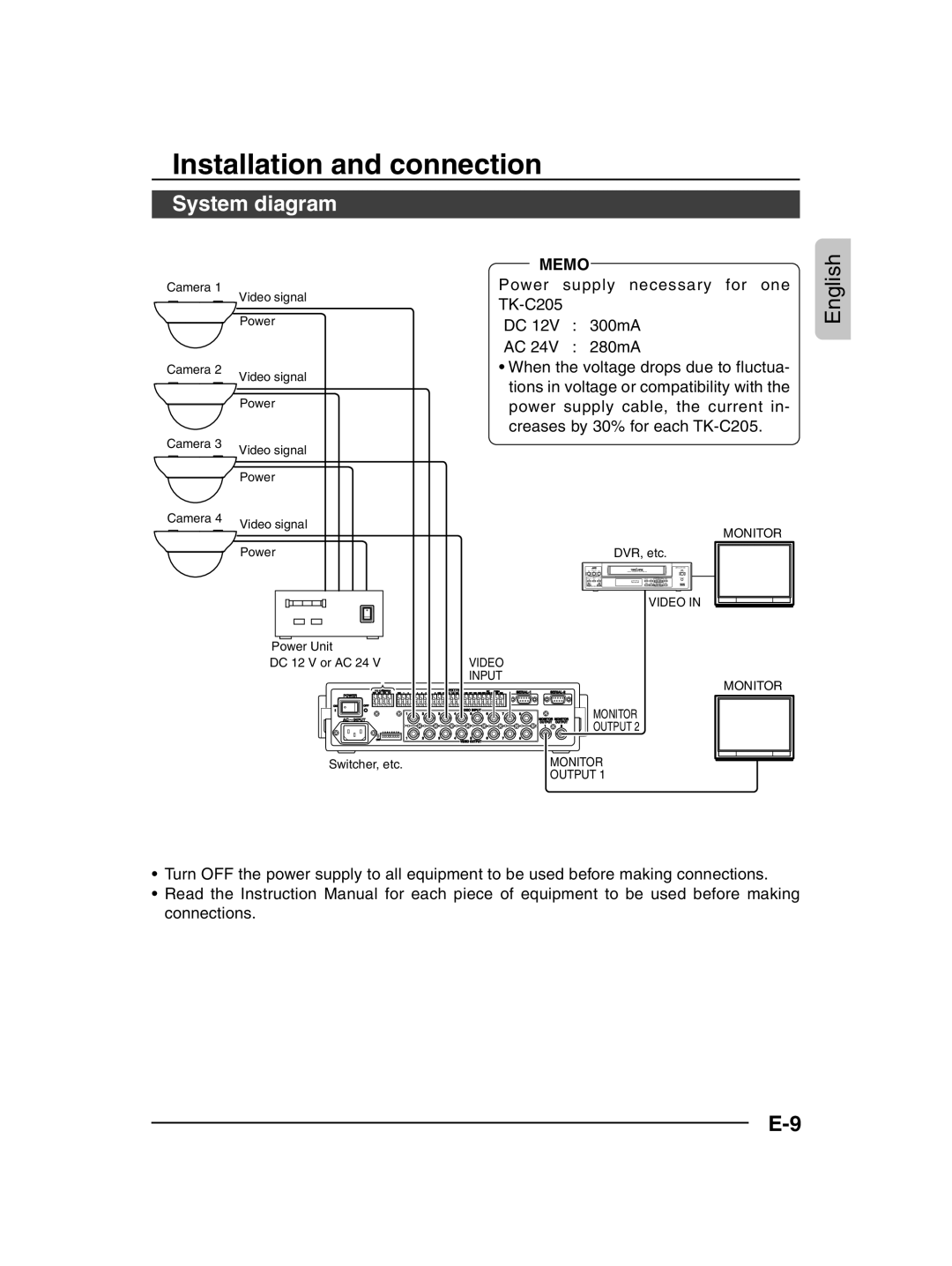
System diagram
Camera 1
| Video signal |
| Power |
Camera 2 | Video signal |
| |
| Power |
Camera 3 | Video signal |
| |
| Power |
MEMO
Power supply necessary for one
DC 12V : 300mA
AC 24V : 280mA
¥When the voltage drops due to fluctua- tions in voltage or compatibility with the power supply cable, the current in- creases by 30% for each
English
Camera 4 | Video signal |
| |
| Power |
Power Unit
DC 12 V or AC 24 VVIDEO
INPUT
| TO CAMERA |
|
|
| COM 1 2 | 3 4 5 6 7 | 8 COM | DATA I / O |
| UNIT CAMERA | COM | ||||
| RX+ RX- TX+ TX- |
|
|
| 9/1 10/2 11/3 12/4 13/5 14/6 15/7 16/8 | COM AUTO ALARM COM SW | |||||||||
POWER |
|
|
|
|
|
|
|
|
|
|
|
|
|
| |
ON | OFF |
|
|
|
|
|
|
|
|
|
|
|
|
|
|
|
|
|
|
|
|
|
|
|
|
|
| VIDEO INPUT |
|
| |
|
|
|
|
|
|
|
| 1 | 2 | 3 | 4 | 5 | 6 | 7 | 8 |
AC | INPUT |
|
|
|
|
|
|
|
|
|
|
|
|
|
|
| 1 | 2 | 3 | 4 | 5 | 6 | 7 | 8 |
|
|
|
|
|
|
|
| ON |
|
|
|
|
|
| 1 | 2 | 3 | 4 | 5 | 6 | 7 | 8 |
|
|
|
|
|
|
|
|
|
|
|
| VIDEO OUTPUT |
|
| |
MONITOR MONITOR OUTPUT OUTPUT
1 ![]() 2
2
MONITOR
DVR, etc.
VIDEO IN
MONITOR
MONITOR
OUTPUT 2
Switcher, etc.
MONITOR OUTPUT 1
¥Turn OFF the power supply to all equipment to be used before making connections.
¥Read the Instruction Manual for each piece of equipment to be used before making connections.
