UFD 510 specifications
The Kathrein UFD 510 is a versatile and highly regarded satellite receiver designed for both consumer and professional applications. Known for its performance and reliability, the UFD 510 is particularly popular among satellite television enthusiasts looking for high-quality viewing experiences. This model boasts a range of features that set it apart in the competitive field of satellite receivers.One of its standout characteristics is its ability to support high-definition (HD) broadcasting. The UFD 510 is capable of receiving and processing HD channels, offering sharp and clear picture quality. This feature is increasingly essential as more broadcasters transition to high-definition content, ensuring that users can enjoy the latest programming without compromise.
The receiver is equipped with advanced digital signal processing technology, allowing it to deliver superior performance even in challenging reception conditions. This includes capabilities to filter out noise and enhance signal quality, ensuring consistent viewing experiences regardless of weather or geographical challenges.
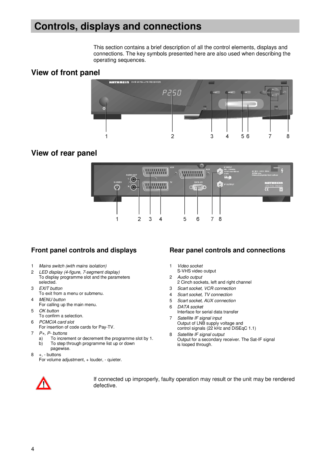
In terms of connectivity, the Kathrein UFD 510 offers multiple input and output options. It features HDMI, composite, and optical audio outputs, making it compatible with a wide range of televisions and home entertainment systems. Additionally, its USB port allows users to connect external storage devices, enabling features such as time-shifting and recording of live television. This flexibility makes it an appealing choice for users who want to personalize their viewing experience.
Another notable feature is its user-friendly interface. The intuitive menu design and remote control make it easy for users to navigate channels and settings, ensuring that even those who are not tech-savvy can operate it with ease. The UFD 510 also supports various languages, accommodating a diverse user base.
The Kathrein UFD 510 is built with durability and energy efficiency in mind. Its compact design allows for easy placement in any entertainment setup, while its low power consumption means it won't significantly impact energy bills.
Overall, the Kathrein UFD 510 is a comprehensive satellite receiver offering a blend of advanced technology, user-friendly features, and reliable performance, making it a compelling choice for anyone looking to enhance their television viewing experience.

