Control Elements, Indications and Connections
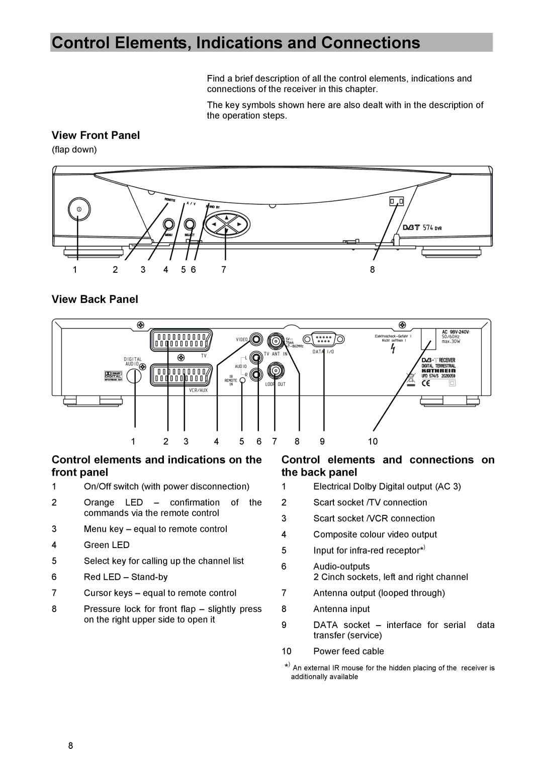
Find a brief description of all the control elements, indications and connections of the receiver in this chapter.
The key symbols shown here are also dealt with in the description of the operation steps.
View Front Panel
(flap down)
1 | 2 | 3 | 4 | 5 6 | 7 | 8 |
View Back Panel
1 | 2 | 3 | 4 | 5 | 6 |
Control elements and indications on the front panel
1On/Off switch (with power disconnection)
2Orange LED – confirmation of the commands via the remote control
3Menu key – equal to remote control
4Green LED
5Select key for calling up the channel list
6Red LED –
7Cursor keys – equal to remote control
8Pressure lock for front flap – slightly press on the right upper side to open it
7 | 8 | 9 | 10 |
Control elements and connections on the back panel
1Electrical Dolby Digital output (AC 3)
2Scart socket /TV connection
3Scart socket /VCR connection
4Composite colour video output
5Input for
6
2 Cinch sockets, left and right channel
7Antenna output (looped through)
8Antenna input
9DATA socket – interface for serial data transfer (service)
10Power feed cable
*) An external IR mouse for the hidden placing of the receiver is additionally available
8
