
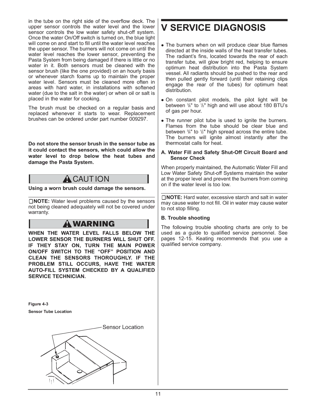
0107 specifications
Keating of Chicago 0107 is a remarkable piece of roofing technology that exemplifies the best in contemporary design and engineering. This groundbreaking product is part of a trend towards more sustainable and efficient building practices, making it an attractive option for modern construction projects.One of the main features of Keating of Chicago 0107 is its robust construction, designed to withstand challenging weather conditions while maintaining integrity over time. The materials used in its production are carefully selected for their durability and performance, ensuring a long lifespan and minimal maintenance needs. This makes it particularly appealing for both residential and commercial applications, where reliability is paramount.
Another significant characteristic of Keating of Chicago 0107 is its advanced insulation properties. By incorporating cutting-edge insulation technology, this roofing system helps to regulate indoor temperatures, contributing to energy efficiency. This feature is especially beneficial in areas with extreme weather, as it reduces the need for additional heating or cooling, thus lowering energy costs.
The aesthetic appeal of Keating of Chicago 0107 is also worth noting. Available in a range of colors and finishes, this roofing solution allows architects and homeowners alike to achieve a tailored look for their buildings. The sleek design complements various architectural styles, from traditional to contemporary, enhancing the overall visual impact of a structure.
In terms of installation, Keating of Chicago 0107 is user-friendly, with a straightforward process that minimizes labor costs and time. This efficiency is crucial in today’s fast-paced construction environment. Moreover, the product is engineered for adaptability, making it suitable for a variety of roof types, including flat and sloped surfaces.
Technologically, Keating of Chicago 0107 incorporates innovations that address common roofing challenges. Features such as water resistance and UV protection ensure that the system remains effective under diverse environmental conditions, preventing issues like leaks or premature wear.
Additionally, sustainability is a focal point with Keating of Chicago 0107. The materials are often sourced from recycled content, and the product can be easily installed in a way that supports eco-friendly building practices. This commitment to sustainability aligns with the growing demand for greener solutions in the construction industry.
In summary, Keating of Chicago 0107 stands out due to its combination of durability, energy efficiency, aesthetic versatility, ease of installation, and commitment to sustainability. It represents a significant advancement in roofing technology, making it a compelling choice for anyone looking to invest in a high-quality roofing solution.