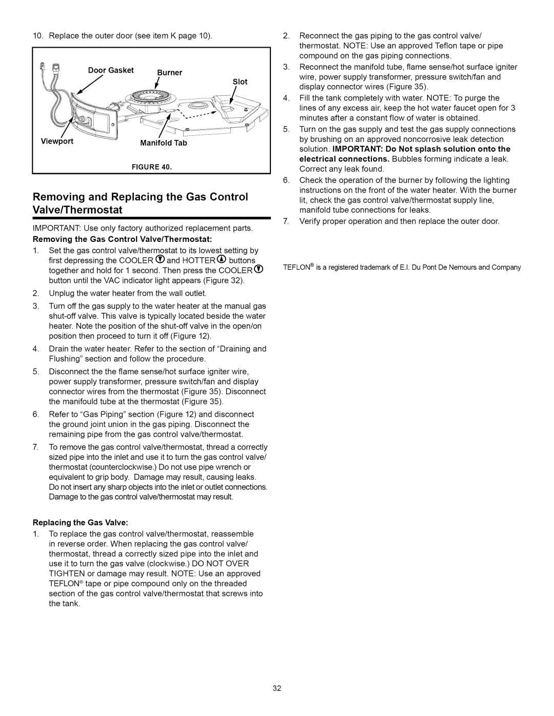
10. Replace the outer door (see item K page 10).

Door Gasket Burner

iSlot

Viewport

Manifold Tab

FIGURE 40.

Removing and Replacing the Gas Control Valve/Thermostat

IMPORTANT: Use only factory authorized replacement parts. Removing the Gas Control Valve/Thermostat:

1.Set the gas control valve/thermostat to its lowest setting by first depressing the COOLER _ and HOTTER(_ buttons together and hold for 1 second. Then press the COOLER(_ button until the VAC indicator light appears (Figure 32).

2.Unplug the water heater from the wall outlet.

3.Turn off the gas supply to the water heater at the manual gas shut-off valve. This valve is typically located beside the water heater. Note the position of the shut-off valve in the open/on position then proceed to turn it off (Figure 12).

4.Drain the water heater. Refer to the section of "Draining and Flushing" section and follow the procedure.

5.Disconnect the the flame sense/hot surface igniter wire, power supply transformer, pressure switch/fan and display connector wires from the thermostat (Figure 35). Disconnect the manifould tube at the thermostat (Figure 35).

6.Refer to "Gas Piping" section (Figure 12) and disconnect the ground joint union in the gas piping. Disconnect the remaining pipe from the gas control valve/thermostat.

7.To remove the gas control valve/thermostat, thread a correctly sized pipe intothe inlet and use it to turn the gas control valve/ thermostat (counterclockwise.) Do not use pipe wrench or equivalent to grip body. Damage may result, causing leaks. Do not insertany sharp objects intothe inletor outlet connections. Damage to the gas control valve/thermostat may result.

Replacing the Gas Valve:

1.To replace the gas control valve/thermostat, reassemble in reverse order. When replacing the gas control valve/ thermostat, thread a correctly sized pipe into the inlet and use it to turn the gas valve (clockwise.) DO NOT OVER TIGHTEN or damage may result. NOTE: Use an approved TEFLON ® tape or pipe compound only on the threaded section of the gas control valve/thermostat that screws into the tank.

2.Reconnect the gas piping to the gas control valve/ thermostat. NOTE: Use an approved Teflon tape or pipe compound on the gas piping connections.

3.Reconnect the manifold tube, flame sense/hot surface igniter wire, power supply transformer, pressure switch/fan and display connector wires (Figure 35).

4.Fill the tank completely with water. NOTE: To purge the

lines of any excess air, keep the hot water faucet open for 3 minutes after a constant flow of water is obtained.

5.Turn on the gas supply and test the gas supply connections by brushing on an approved noncorrosive leak detection solution. IMPORTANT: Do Not splash solution onto the electrical connections. Bubbles forming indicate a leak. Correct any leak found.

6.Check the operation of the burner by following the lighting instructions on the front of the water heater. With the burner

lit, check the gas control valve/thermostat supply line, manifold tube connections for leaks.

7.Verify proper operation and then replace the outer door.

TEFLON ® is a registered trademark of E.I. Du Pont De Nemours and Company

32

Page 32
Image 32
Kenmore 153.33264, 153.33262 Removing and Replacing the Gas Control Valve/Thermostat, Door Gasket Burner ISlot Viewport

153.33262, 153.33264 specifications

The Kenmore 153.33262 and 153.33264 are highly versatile and efficient portable air conditioners designed to provide optimal cooling solutions for indoor spaces. These models stand out in their class due to their advanced features, technologies, and user-friendly characteristics, making them suitable for a variety of environments, from small apartments to large rooms.

One of the primary features of both the Kenmore 153.33262 and 153.33264 is their high cooling capacity. With powerful BTUs, they can effectively cool spaces up to a specified square footage. This capability ensures that users can maintain a comfortable indoor climate even during the hottest summer months. Their energy efficiency is another notable aspect, allowing homeowners to enjoy cooler air without incurring exorbitant energy bills.

The two models are equipped with various modes of operation, including cooling, fan, and dehumidifying modes. This multifunctionality allows users to customize their comfort based on prevailing weather conditions. For instance, the dehumidifying mode effectively reduces excess moisture in the air, creating a more comfortable environment, particularly in humid regions.

Both air conditioners come with a user-friendly digital interface that features an easy-to-read LED display. The interface allows for straightforward adjustments to the temperature, fan speed, and operating modes. Furthermore, remote control functionality enhances convenience, enabling users to change settings from across the room.

In terms of technology, these models incorporate a self-evaporating system that minimizes the need for manual water drainage. This feature is particularly advantageous for users who prefer low-maintenance options. Additionally, both units feature a washable air filter, designed to capture dust and allergens, improving air quality and ensuring that the units operate efficiently.

Portability is another significant characteristic of the Kenmore 153.33262 and 153.33264. Built-in caster wheels and side handles allow for easy movement from room to room, making them ideal for temporary cooling needs. The easy installation process and included window exhaust kit mean users can set up the units quickly without requiring professional assistance.

In conclusion, the Kenmore 153.33262 and 153.33264 portable air conditioners offer a robust combination of high cooling performance, energy efficiency, and user-friendly features. Their advanced technologies and versatile functionalities make them an ideal choice for those seeking effective indoor air conditioning solutions.