5.1.1Fuel Lines
Note: Keep fuel lines away from the exhaust system.
Routing fuel lines. Take care when routing the fuel line from the fuel tank to the generator set. Keep the fuel lines as short as possible but maintain adequate clearance from the exhaust system. Route the fuel lines along the frame or
Sizing fuel inlet and return lines. Size the fuel line to handle the flow of fuel and to withstand road shock and
Flexible hose sections. If a metal fuel line draws fuel from the fuel tank, install a flexible hose section to connect the metal line to the fuel pump. The flexible section allows generator set vibrational motion during operation. See Section 7 for the fuel inlet and the fuel return connection points.
Note:
5.2 Fuel Filters or Strainers
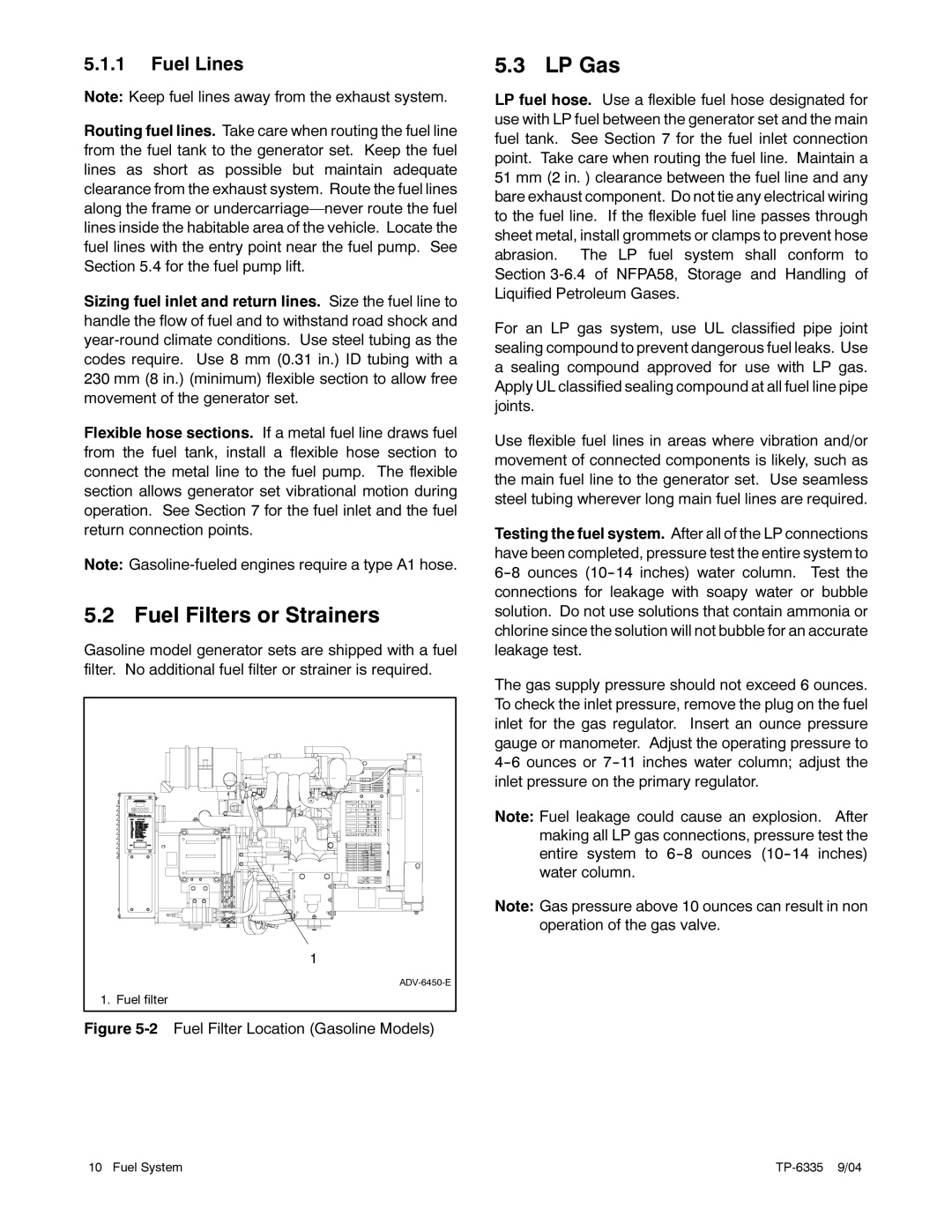
Gasoline model generator sets are shipped with a fuel filter. No additional fuel filter or strainer is required.
| 1 |
| |
1. | Fuel filter |
Figure 5-2 Fuel Filter Location (Gasoline Models)
5.3 LP Gas
LP fuel hose. Use a flexible fuel hose designated for use with LP fuel between the generator set and the main fuel tank. See Section 7 for the fuel inlet connection point. Take care when routing the fuel line. Maintain a 51 mm (2 in. ) clearance between the fuel line and any bare exhaust component. Do not tie any electrical wiring to the fuel line. If the flexible fuel line passes through sheet metal, install grommets or clamps to prevent hose abrasion. The LP fuel system shall conform to Section
For an LP gas system, use UL classified pipe joint sealing compound to prevent dangerous fuel leaks. Use a sealing compound approved for use with LP gas. Apply UL classified sealing compound at all fuel line pipe joints.
Use flexible fuel lines in areas where vibration and/or movement of connected components is likely, such as the main fuel line to the generator set. Use seamless steel tubing wherever long main fuel lines are required.
Testing the fuel system. After all of the LP connections have been completed, pressure test the entire system to
The gas supply pressure should not exceed 6 ounces. To check the inlet pressure, remove the plug on the fuel inlet for the gas regulator. Insert an ounce pressure gauge or manometer. Adjust the operating pressure to
Note: Fuel leakage could cause an explosion. After making all LP gas connections, pressure test the entire system to
Note: Gas pressure above 10 ounces can result in non operation of the gas valve.
10 Fuel System |