7.2 Electrical Connections

Several electrical connections must be made between the generator set and other components of the system for proper operation. Because of the large number of accessories and possible combinations, this manual does not address specific applications. Refer to the submittal catalog accessory drawings and wiring diagrams for connection and location. Most field-installed accessory kits include installation instructions.

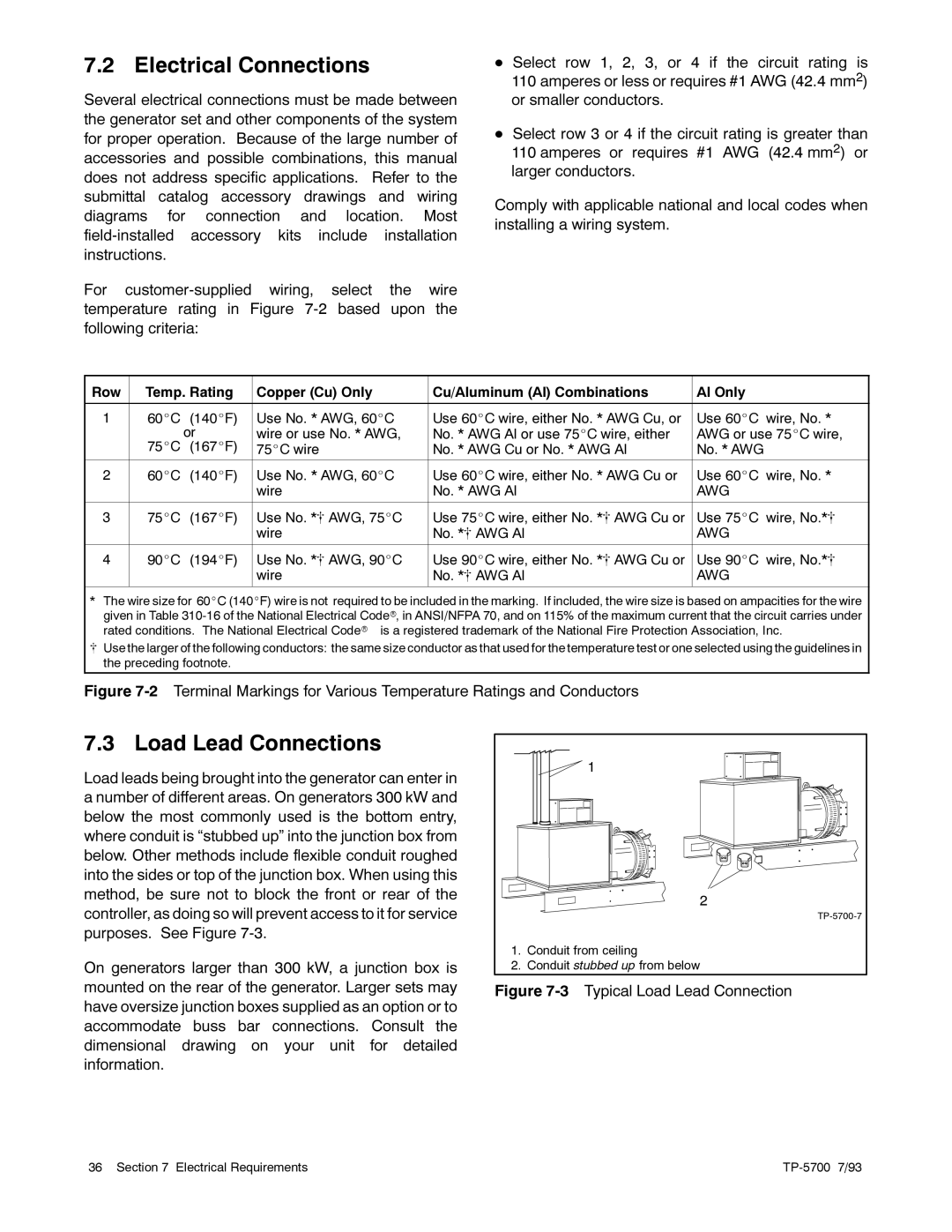
For customer-supplied wiring, select the wire temperature rating in Figure 7-2 based upon the following criteria:

DSelect row 1, 2, 3, or 4 if the circuit rating is 110 amperes or less or requires #1 AWG (42.4 mm2) or smaller conductors.

DSelect row 3 or 4 if the circuit rating is greater than 110 amperes or requires #1 AWG (42.4 mm2) or larger conductors.

Comply with applicable national and local codes when installing a wiring system.

Row

Temp. Rating

Copper (Cu) Only

Cu/Aluminum (Al) Combinations

Al Only


1

60_C (140_F)

Use No. * AWG, 60_C

Use 60_C wire, either No. * AWG Cu, or

Use 60_C wire, No. *


or

wire or use No. * AWG,

No. * AWG Al or use 75_C wire, either

AWG or use 75_C wire,


75_C (167_F)

75_C wire

No. * AWG Cu or No. * AWG Al

No. * AWG


2

60_C

(140_F)

Use No. * AWG, 60_C

Use 60_C wire, either No. * AWG Cu or

Use 60_C wire, No. *


wire

No. * AWG Al

AWG


3

75_C

(167_F)

Use No. *[ AWG, 75_C

Use 75_C wire, either No. *[ AWG Cu or

Use 75_C wire, No.*[


wire

No. *[ AWG Al

AWG


4

90_C

(194_F)

Use No. *[ AWG, 90_C

Use 90_C wire, either No. *[ AWG Cu or

Use 90_C wire, No.*[


wire

No. *[ AWG Al

AWG


* The wire size for 60_C (140_F) wire is not required to be included in the marking. If included, the wire size is based on ampacities for the wire given in Table 310-16 of the National Electrical Coder, in ANSI/NFPA 70, and on 115% of the maximum current that the circuit carries under rated conditions. The National Electrical Coder is a registered trademark of the National Fire Protection Association, Inc.

[ Use the larger of the following conductors: the same size conductor as that used for the temperature test or one selected using the guidelines in the preceding footnote.

Figure 7-2 Terminal Markings for Various Temperature Ratings and Conductors

7.3 Load Lead Connections

Load leads being brought into the generator can enter in a number of different areas. On generators 300 kW and below the most commonly used is the bottom entry, where conduit is “stubbed up” into the junction box from below. Other methods include flexible conduit roughed into the sides or top of the junction box. When using this method, be sure not to block the front or rear of the controller, as doing so will prevent access to it for service purposes. See Figure 7-3.

On generators larger than 300 kW, a junction box is mounted on the rear of the generator. Larger sets may have oversize junction boxes supplied as an option or to accommodate buss bar connections. Consult the dimensional drawing on your unit for detailed information.


1


2


TP-5700-7

1.

Conduit from ceiling

2.

Conduit stubbed up from below

Figure 7-3 Typical Load Lead Connection

36 Section 7 Electrical Requirements

TP-5700 7/93

Page 48
Image 48
Kohler 20--2800 kW manual Electrical Connections, Load Lead Connections

20--2800 kW specifications

The Kohler 20-2800 kW generator series is renowned for its exceptional performance and reliability, making it a prime choice for various industrial and commercial applications. Designed for continuous and backup power generation, these generators are capable of providing robust energy solutions for facilities that demand high capacity and efficiency.

One of the standout features of the Kohler 20-2800 kW series is its advanced technology integration. Kohler utilizes the latest in digital control systems, ensuring precise monitoring and management of generator functions. The generator's control panel provides real-time data on power output, fuel consumption, and operating conditions, allowing operators to make informed decisions quickly.

In terms of fuel efficiency, the Kohler generators are engineered to minimize operational costs while maximizing performance. The series includes options for both diesel and natural gas, offering flexibility depending on user requirements and availability. The efficient fuel consumption not only supports cost savings but also aligns with environmental standards, reducing emissions during operation.

Durability and reliability are key characteristics of this generator series. Kohler buildings are constructed using high-quality materials and components that withstand harsh environmental conditions. System redundancy features and robust cooling systems ensure that the generators can operate continuously without failure, making them ideal for critical power needs.

The Kohler 20-2800 kW series also includes noise-reducing technology, making them suitable for installations in noise-sensitive environments. With options for acoustic enclosures, these generators comply with local noise regulations while delivering powerful performance.

Safety features are integrated into the generator design, including automatic shutdown systems for over-speed, low oil pressure, and high water temperature, ensuring that the equipment operates safely during emergencies.

The modular design of the Kohler 20-2800 kW allows for easy installation and maintenance. Access points for service and diagnostics are strategically placed for convenience, reducing downtime and improving efficiency in upkeep.

Overall, the Kohler 20-2800 kW generator series stands out as a dependable powerhouse, combining advanced technology, fuel efficiency, durability, and safety features to meet the demands of various industries. Whether for data centers, manufacturing facilities, or large commercial buildings, Kohler's commitment to quality and innovation makes these generators an exemplary choice for reliable power generation.