The connection from the radiator duct flange to the ductwork should be heavy canvas, silicone or similar flexible material to prevent noise and vibration transmission. Sheet metal ductwork should be self-supporting. In general, the outlet duct should have an unrestricted area 150% greater than that enclosed by the radiator duct flange. The inlet air opening should be at least as large as the outlet but preferably 50% larger. If screens, louvers or filters are used, openings should be increased in size according to the recommendations given in the “Air Requirements, General” section. Ductwork should be designed to allow ease of service in the event the radiator would have to be removed.

Air inlet and outlet locations should be chosen to prevent air recirculation inside or outside the enclosure. Consideration should also be given to prevailing winds, facing inlets into the expected winds and outlets on the downwind side where possible. Inlets and outlets should be located where they will not be blocked by accumulated snow or any other obstruction. Keep in mind that the exhaust air of larger units is both high-volume and high velocity. It may be accompanied by a high sound level and should be directed away from areas that may be occupied by people or animals.

Be sure to design any temperature controlling louvers so that inlet air is not restricted to the point that pressure inside the building is reduced. Low pressure can cause pilot lights on gas fired appliances to be extinguished or problems with the building ventilation system.

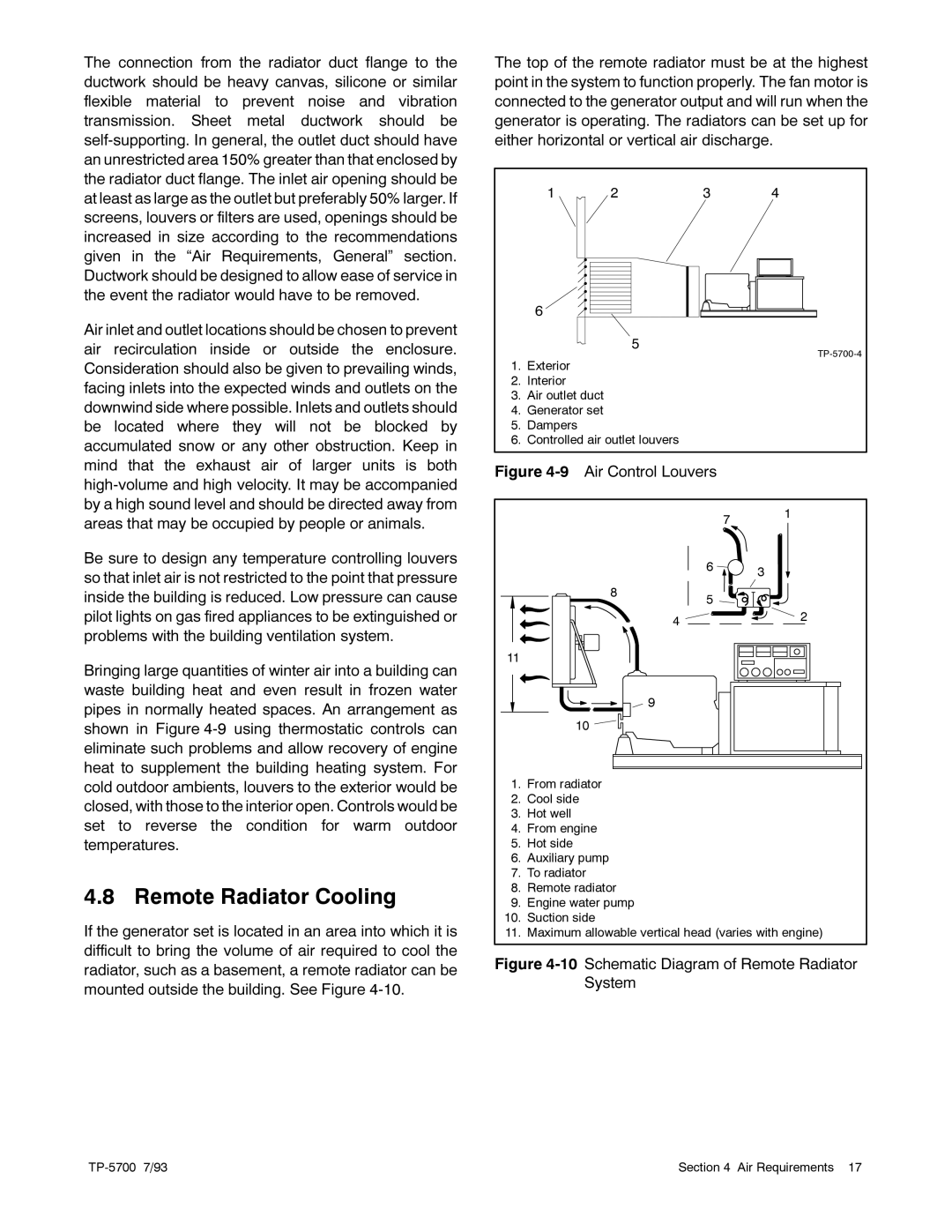
Bringing large quantities of winter air into a building can waste building heat and even result in frozen water pipes in normally heated spaces. An arrangement as shown in Figure 4-9 using thermostatic controls can eliminate such problems and allow recovery of engine heat to supplement the building heating system. For cold outdoor ambients, louvers to the exterior would be closed, with those to the interior open. Controls would be set to reverse the condition for warm outdoor temperatures.

4.8 Remote Radiator Cooling

If the generator set is located in an area into which it is difficult to bring the volume of air required to cool the radiator, such as a basement, a remote radiator can be mounted outside the building. See Figure 4-10.

The top of the remote radiator must be at the highest point in the system to function properly. The fan motor is connected to the generator output and will run when the generator is operating. The radiators can be set up for either horizontal or vertical air discharge.


1

2

3

4


6


5


TP-5700-4


1.

Exterior


2.

Interior


3.

Air outlet duct


4.

Generator set


5.

Dampers


6.

Controlled air outlet louvers


Figure 4-9 Air Control Louvers

7 1

6 3

8

5

4

2


11

9

10

1.From radiator

2.Cool side

3.Hot well

4.From engine

5.Hot side

6.Auxiliary pump

7.To radiator

8.Remote radiator

9.Engine water pump

10.Suction side

11.Maximum allowable vertical head (varies with engine)

Figure 4-10 Schematic Diagram of Remote Radiator System

TP-5700 7/93

Section 4 Air Requirements 17

Page 29
Image 29
Kohler 20--2800 kW manual Remote Radiator Cooling, Air Control Louvers

20--2800 kW specifications

The Kohler 20-2800 kW generator series is renowned for its exceptional performance and reliability, making it a prime choice for various industrial and commercial applications. Designed for continuous and backup power generation, these generators are capable of providing robust energy solutions for facilities that demand high capacity and efficiency.

One of the standout features of the Kohler 20-2800 kW series is its advanced technology integration. Kohler utilizes the latest in digital control systems, ensuring precise monitoring and management of generator functions. The generator's control panel provides real-time data on power output, fuel consumption, and operating conditions, allowing operators to make informed decisions quickly.

In terms of fuel efficiency, the Kohler generators are engineered to minimize operational costs while maximizing performance. The series includes options for both diesel and natural gas, offering flexibility depending on user requirements and availability. The efficient fuel consumption not only supports cost savings but also aligns with environmental standards, reducing emissions during operation.

Durability and reliability are key characteristics of this generator series. Kohler buildings are constructed using high-quality materials and components that withstand harsh environmental conditions. System redundancy features and robust cooling systems ensure that the generators can operate continuously without failure, making them ideal for critical power needs.

The Kohler 20-2800 kW series also includes noise-reducing technology, making them suitable for installations in noise-sensitive environments. With options for acoustic enclosures, these generators comply with local noise regulations while delivering powerful performance.

Safety features are integrated into the generator design, including automatic shutdown systems for over-speed, low oil pressure, and high water temperature, ensuring that the equipment operates safely during emergencies.

The modular design of the Kohler 20-2800 kW allows for easy installation and maintenance. Access points for service and diagnostics are strategically placed for convenience, reducing downtime and improving efficiency in upkeep.

Overall, the Kohler 20-2800 kW generator series stands out as a dependable powerhouse, combining advanced technology, fuel efficiency, durability, and safety features to meet the demands of various industries. Whether for data centers, manufacturing facilities, or large commercial buildings, Kohler's commitment to quality and innovation makes these generators an exemplary choice for reliable power generation.